A closed path followed by magnetic flux is known as a magnetic circuit. In a magnetic circuit, flux starts from one point and finishes at the same point. A magnetic circuit usually consists of magnetic materials having high permeability such as iron, soft steel, etc. since they offer small opposition to magnetic flux.
The magnetic flux is usually produced by an electric current through a solenoid (having a large number of turns. There are three types of magnetic circuits:
- Series Magnetic Circuit
- Parallel Magnetic Circuit
- Series-parallel Magnetic Circuits
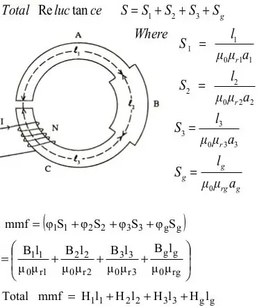
Series Magnetic Circuit
A magnetic circuit that has many parts of different dimensions and materials connected in series is called a series magnetic circuit.
Consider a composite magnetic circuit consisting of three parts having different lengths, areas of cross-sections, and relative permeabilities. It also has an air gap.
In this case, the reluctance of each part will be different depending upon the dimensions and relative permeabilities of that part. The total reluctance will be the sum of the reluctance of individual parts. The same flux will flow through complete circuits.
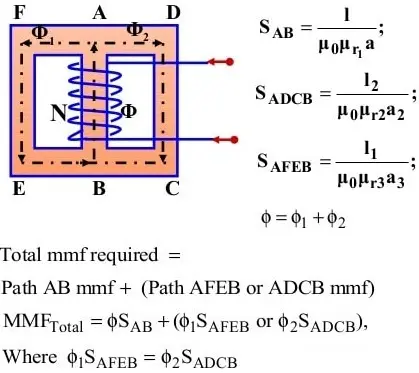
Parallel Magnetic Circuit
A magnetic circuit that has more than one path for the magnetic flux is called a parallel magnetic circuit. It is similar to a parallel electric circuit that has more than one path for electric current to flow.
Consider a parallel magnetic circuit shown in Figure. A current-carrying coil is wound on the central limb. The flux set up by this coil is divided at A into two paths i.e.
- Flux ɸ1 passes along the path AFEB,
- Flux ɸ2 passes along the path ADCB
- It is clear that ɸ = ɸ1 + ɸ2
Here the two magnetic paths AFEB and ADCB are in parallel, the total MMF required for this parallel circuit will be equal to the MMF required for any of the above-mentioned paths.
Compare Series and Parallel Magnetic Circuit
Magnetic circuits, like their electrical counterparts, can be arranged in series or parallel configurations. Each arrangement has distinct properties that affect the overall magnetic behavior of the circuit. Here’s a breakdown of the key differences:
Flow of Magnetic Flux (Φ): In a series circuit, the same magnetic flux (Φ) flows through all parts of the circuit.But in a parallel circuit, the total magnetic flux is divided and flows through each branch independently.
Magneto Motive Force (MMF): The total MMF (magneto motive force) required to drive the flux through the entire series circuit is the sum of the MMF needed for each section. But, in a Parallel circuit, the MMF required across each parallel branch is the same.
Reluctance (R): The total reluctance of a series circuit is the sum of the reluctances of each section. Adding more reluctant sections (like narrow passages) in series makes it harder for the flux to flow overall.
Whereas, the total reluctance of a parallel circuit is equal to the reciprocal of the sum of the reciprocals of the reluctances of each branch. This reflects how easier paths (wider passages) in parallel offer less overall resistance to the flux.
Applications: Series circuits are often used where a concentrated magnetic flux is needed in a specific location, such as in electromagnets.
Parallel circuits are useful when high total flux is required, or when different path lengths or materials necessitate independent control of flux in each branch. This can be seen in some motor designs and transformers.
Important Terms of Magnetic Circuits
Magnetic Flux Density (B): The flux per unit area is defined as the magnetic flux density. It is measured in a plane perpendicular to flux.
- Magnetic Flux Density, B = φ ÷ A
- Units: Weber per meter square (Wb/m2) or Tesla (T).
Magnetic Field Intensity: The magnetic field strength or magnetic field intensity is given by MMF per unit length of the magnetic circuit.
- Magnetic Field Intensity, H = (NI) ÷ l
- Units: AT/m.
Where N = Number of turns of the magnetizing coil; I = Current through the coil; l = Length of magnetic material in meters. The magnetic field intensity is also known as magnetic field strength or magnetizing force.
Permeability: The ability of a material to carry the magnetic lines of flux is known as the permeability of that material. The magnetic lines of force can pass through high-permeability materials like iron, and steel, very easily. Low permeability materials like wood etc. don’t allow the flux lines to pass through them easily.
Absolute Permeability: It is the ratio of flux density (B) in a particular medium to the magnetic field strength (H) that produces magnetic flux density. It is denoted by µ.
- Absolute Permeability, µ = µo µr
- Units: Henry/meter (H/m)
Permeability of the Air/Space/Vacuum: If a magnet is kept in air or vacuum, then the ratio of flux density (B) and magnetic field strength (H) is defined as the permeability of free space. It is denoted by µo.
- Permeability of Free Space, µo = 4π x 10-7 H/m
Relative Permeability: The ratio of the permeability of material to the permeability of vacuum or air is known as relative permeability.
- Relative Permeability, µr = µ ÷ µo
- It has no units.
The relative permeability of vacuum, air, and all non-magnetic materials is 1. The relative permeability of all the magnetic materials is very high. For example, the relative permeability of permalloy (nickel 78% and iron 22%) is about 50000.
Magneto Motive Force (MMF): The magneto-motive force is the driving force that produces the magnetic flux. The magnetic field intensity (H) is decided by MMF.
- Magneto-motive Force, MMF = NI
- Units: Ampere Turns (AT)
Where N = Number of turns of the magnetizing coil; I = current through the coil.
Reluctance (S): It is opposition offered to the flow of magnetic flux by the magnetic material.
Reluctance, S = l ÷ (µ x a)
Where l = length of the magnetic path in meters; a = area of the cross-section of the magnetic path in meter square; µ = µoµr (absolute permeability of medium in H/m.)
Therefore,
- Reluctance, S = l ÷ (µoµra)
- Unit: AT/Wb
The reluctance is also given by the ratio of the MMF and the amount of flux produced.
- i.e., Reluctance, S = MMF ÷ flux
- Reluctance, S = (NI) ÷ φ
Permeance: The permeance of a material represents the ease with which magnetic flux can be produced in that material. It is reciprocal of reluctance. Its unit is Wb/AT or Henry.
Magnetic Susceptibility: The magnetization of a material is proportional to the field and the proportionality constant is called the magnetic susceptibility. In other words, it can be defined as the ratio of magnetization M to magnetizing force H i.e.
- Magnetic Susceptibility, Xm = M/H
- It is a dimensionless quantity.
It is a measure of how easily a material is magnetized in a magnetizing field. Its value for vacuum is zero as there can be no magnetization in the vacuum.
We can classify materials in terms of Xm. Materials with positive values of Xm are paramagnetic and those with negative values of Xm are diamagnetic. For ferromagnetic materials, Xm is positive and very large.
Leakage Factor of Magnetic Circuits (λ)
The part of the total magnetic flux which flows through the magnetic circuit is called useful magnetic flux. However, the magnetic flux which does not completely pass through the magnetic path, but partially passes through the air is called leakage magnetic flux.
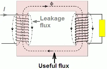
Mathematically, φtotal = φuseful + φleakage
The ratio of total flux produced to the useful flux is called the leakage factor or leakage coefficient.
- Leakage factor, λ = φtotal / φuseful
The value of the leakage factor is always greater than unity. Typical values of leakage factor are from 1.12 to 1.25. In magnetic circuits, the magnetic leakage can be minimized by placing the exciting coils as close as possible to the points where the flux is to be utilized.
Fringing in Magnetic Circuits
The magnetic lines of force repel each other while passing through a non-magnetic material. Due to this when the flux lines cross the air gap, they tend to bulge outwards. This effect is known as fringing.
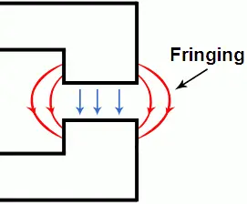
The effect of fringing is to make the effective air gap area larger than that of the magnetic path and consequently, the flux density in the air gap is reduced. The effect of fringing depends upon the length of the air gap.
To minimize fringing, the air gap length is kept as small as possible. The effect of fringing can be neglected if the air gap length is very small as compared to its width.