The AC induction motor is the dominant motor technology in use today, representing more than 90 percent of installed motor capacity. Induction motors are available in single-phase (1ϕ) and three-phase (3ϕ) configurations, in sizes ranging from fractions of a horsepower to tens of thousands of horsepower. They may run at fixed speeds – most commonly 900, 1200, 1800, or 3600 rpm – or be equipped with an adjustable-speed drive.
Induction Motor Working Principle
The induction motor works on the principle of electromagnetic induction. In this motor, a magnetic field in the stator is made to rotate electrically around and around in a circle. Another magnetic field in the rotor is made to follow the rotation of this field pattern by being attracted and repelled by the stator field. Because the rotor is free to turn, it follows the rotating magnetic field in the stator.
The induction motor is so named because no external voltage is applied to its rotor. There are no slip rings or any DC excitation supplied to the rotor. Instead, the AC current in the stator induces a voltage across an air gap and into the rotor winding to produce rotor current and associated magnetic field. The stator and rotor magnetic fields then interact and cause the rotor to turn.
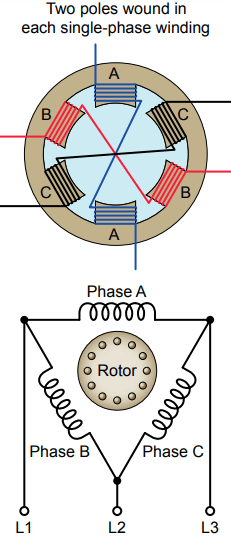
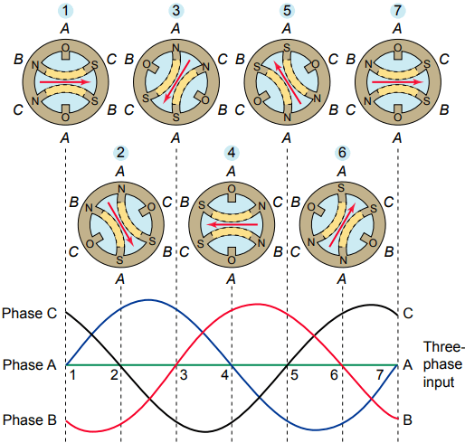
Figure 1 illustrates the concept of a rotating magnetic field as it applies to the stator of a three-phase induction motor. The operation can be summarized as follows:
- Three sets of windings are placed 120 electrical degrees apart with each set connected to one phase of the three-phase power supply.
- When three-phase current passes through the stator windings, a rotating magnetic field effect is produced that travels around the inside of the stator core.
- Polarity of the rotating magnetic field is shown at six selected positions marked off at 60 degree intervals on the sine waves representing the current flowing in the three phases, A, B, and C.
- In the example shown, the magnetic field will rotate around the stator in a clockwise direction.
- Simply interchanging any two of the three-phase power input leads to the stator windings reverses direction of rotation of the magnetic field.
- The number of poles is determined by how many times a phase winding appears. In this example, each winding appears twice, so this is a two-pole stator.
Synchronous Speed
There are two ways to define AC motor speed. First is synchronous speed. The synchronous speed of an AC motor is the speed of the stator’s magnetic field rotation. This is the motor’s ideal theoretical, or mathematical, speed, since the rotor will always turn at a slightly slower rate.
The other way motor speed is measured is called actual speed. This is the speed at which the shaft rotates. The nameplate of most AC motors lists the actual motor speed rather than the synchronous speed.
The speed of the rotating magnetic field varies directly with the frequency of the power supply and inversely with the number of poles constructed on the stator winding. This means the higher the frequency, the greater the speed and the greater the number of poles the slower the speed.
Motors designed for 60 Hz use have synchronous speeds of 3,600, 1,800, 1,200, 900, 720, 600, 514, and 450 rpm.
The synchronous speed of an AC motor can be calculated by the formula:
NS = 120f/P
Where NS = synchronous speed in rpm; f = frequency, Hz, of the power supply; P = number of poles wound in each of the single-phase windings.
The AC induction motor is by far the most commonly used motor because it is relatively simple and can be built at less cost than other types. Induction motors are made in both three-phase and single-phase types.
A three-phase motor stator winding consists of three separate groups of coils, called phases, and designated A, B, and C. The phases are displaced from each other by 120 electrical degrees and contain the same number of coils, connected for the same number of poles.
Poles refer to a coil or group of coils wound to produce a unit of magnetic polarity. The number of poles a stator is wound for will always be an even number and refers to the total number of north and south poles per phase.
An induction motor rotor can be either wound rotor or a squirrel cage rotor. The majority of commercial and industrial applications usually involve the use of a three-phase squirrel-cage induction motor.
Squirrel Cage Induction Motor
A typical squirrel-cage rotor is shown in Figure 3. The rotor is constructed using a number of single bars short-circuited by end rings and arranged in a hamster-wheel or squirrel-cage configuration.

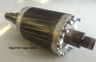
When voltage is applied to the stator winding, a rotating magnetic field is established. This rotating magnetic field causes a voltage to be induced in the rotor, which, because the rotor bars are essentially single-turn coils, causes currents to flow in the rotor bars.
These rotor currents establish their own magnetic field, which interacts with the stator magnetic field to produce a torque. The resultant production of torque spins the rotor in the same direction as the rotation of the magnetic field produced by the stator.
In modern induction motors, the most common type of rotor has cast-aluminum conductors and short-circuiting end rings.
The resistance of the squirrel-cage rotor has an important effect on the operation of the motor. A high-resistance rotor develops a high starting torque at low starting current. A low-resistance rotor develops low slip and high efficiency at full load.
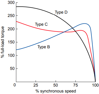
Figure 4 shows how motor torque varies with rotor speed for three NEMA-type squirrel-cage induction motors:
NEMA Design B: Considered a standard type with normal starting torque, low starting current, and low slip at full load. Suitable for a broad variety of applications, such as fans and blowers, that require normal starting torque.
NEMA Design C: This type has higher than standard rotor resistance, which improves the rotor power factor at start, providing more starting torque. When loaded, however, this extra resistance causes a greater amount of slip. Used for equipment, such as a pump, that requires a high starting torque.
NEMA Design D: The even higher rotor resistance of this type produces a maximum amount of starting torque. This type is suitable for equipment with very high inertia starts such as cranes and hoists.
Operating characteristics of the squirrel-cage motor include the following:
- The motor normally operates at essentially constant speed, close to the synchronous speed.
- Large starting currents required by this motor can result in line voltage fluctuations.
- Interchanging any two of the three main power lines to the motor reverses the direction of rotation.
Induction Motor Slip
The rotor does not revolve at synchronous speed, but tends to slip behind. Slip is what allows a motor to turn. If the rotor turned at the same speed at which the field rotates, there would be no relative motion between the rotor and the field and no voltage induced.
Because the rotor slips with respect to the rotating magnetic field of the stator, voltage and current are induced in the rotor. The difference between the speed of the rotating magnetic field and the rotor in an induction motor is known as slip and is expressed as a percentage of the synchronous speed as follows:
Percent slip = (Synchronous speed – Actual speed) x 100/Synchronous speed
The slip increases with load and is necessary to produce useful torque. The usual amount of slip in a 60-Hz, three-phase motor is 2 or 3 percent.
Loading of Induction Motor
Loading of an induction motor is similar to that of a transformer in that the operation of both involves changing flux linkages with respect to a primary (stator) winding and secondary (rotor) winding. The no-load current is low and similar to the exciting current in a transformer.
Thus, it is composed of a magnetizing component that creates the revolving flux and a small active component that supplies the windage and friction losses in the rotor plus the iron losses in the stator.
When the induction motor is under load, the rotor current develops a flux that opposes and, therefore, weakens the stator flux. This allows more current to flow in the stator windings, just as an increase in the current in the secondary of a transformer results in a corresponding increase in the primary current.
You may recall that power factor (PF) is defined as the ratio of the actual (or true) power (watts) to the apparent power (volt-amperes) and is a measure of how effectively the current drawn by a motor is converted into useful work.
The motor exciting current and reactive power under load remain about the same as at no load. For this reason, whenever a motor is operating with no load, the power factor is very low in comparison to when it is operating at full load.
At full load the PF ranges from 70 percent for small motors to 90 percent for larger motors. Induction motors operate at their peak efficiency if they are sized correctly for the load that they will drive.
Oversized motors not only operate inefficiently, but they also carry a higher first cost than right-sized units. The moment a motor is started, during the acceleration period, the motor draws a high inrush current. This inrush current is also called the locked-rotor current.
Common induction motors, started at rated voltage, have locked- rotor starting currents of up to 6 times their nameplate full-load current. The locked-rotor current depends largely on the type of rotor bar design and can be determined from the NEMA design code letters listed on the nameplate.
High locked-rotor motor current can create voltage sags or dips in the power lines, which may cause objectionable light flicker and problems with other operating equipment. Also, a motor that draws excessive current under locked-rotor conditions is more likely to cause nuisance tripping of protection devices during motor start-ups.
Thanks for reading about “induction motor working principle”.