The working principle of DC motor can be stated as follows:
When a current-carrying conductor is placed in a magnetic field, it experiences a force.
In the case of a DC motor, the magnetic field is produced by the field winding. And the armature winding is connected to the external supply voltage hence it plays the role of a current-carrying conductor placed in the magnetic field.
Therefore a force is exerted on the armature placed in the magnetic field, it starts rotating. The direction of rotation of the DC motor can be determined by Fleming’s left-hand rule.
Working Principle of DC Motor
When a DC motor is switched on, a direct current flows through the armature conductors and field windings. This flow of current produces an armature field and pole field.
Now, there are two magnetic fields in the air gap between field shoes and armature. These two fields react with each other to rotate the armature.
The commutator reverses the direction of the flow of the armature current at regular intervals so that the armature field is always repelled by the pole field.
Since the armature is continuously repelled by the field poles, it keeps rotating the armature in the same direction.
Working Principle of DC Motor – Illustratation
To illustrate the working principle of DC motor, consider Figure 1, which shows a simplified arrangement of two brushes and a two-piece commutator. The leads of the rotor coil, which are situated between a magnetic field, are attached to the commutator.
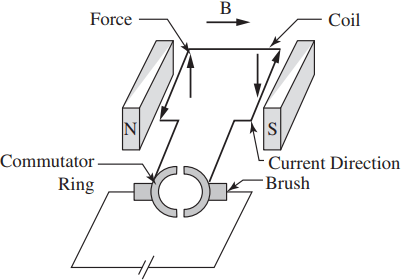
A brush-type DC motor develops a torque (and hence rotation of the rotor) when a current flows in the rotor coils through the magnetic field created by the stator. The torque is the result of the two equal but opposite forces acting on the sides of the coil.
The force is given by Lorentz’s law which states that when a conductor carries a current through a magnetic field, a force acts on the conductor and is given as the vector cross product of the current and the magnetic field, or mathematically:
F = I x B
Where I is the current vector and B is the magnetic field vector. For the current arrangement shown in Figure 1, these forces will cause the coil to rotate clockwise as seen from the brush end.
Without the use of a commutator to maintain the direction of the current, the torque direction will reverse the moment the coil passes through the vertical plane (called the commutation plane), producing no useful motion.
Using a two-piece commutator, the resulting torque will not be smooth and will exhibit the ripple shown in Figure 2(a).
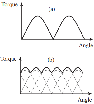
Note that the torque is maximum when the coil is horizontal because, at this position, the moment arm distance between the forces acting on the coil is maximum.
Similarly, the torque is zero when the coil is in the commutation plane because the moment arm distance is zero.
In general, the torque is a function of the sine of the angle between the magnetic field direction and the vector normal to the plane of the coil, which is 90° for the coil position shown in Figure 1.
If we had used a six-piece commutator (and also three coils, one for each commutator pair) instead of using a two-piece commutator, the torque would be smoother (Figure 2(b)) since the torque at any point in time is the sum of all the torques in all the coils. If the stator magnetic field could be made radial, then the ripple is eliminated since the angle will always be 90°.
To improve the torque characteristics, commercial motors have a commutator that is split into 50 or more segments.
Note that the mechanical contact between the brushes and the commutator leads to the wear of these components as well as the formation of arcs which require these components to be serviced periodically.
Counter Electromotive Force (CEMF) in DC Motor
As the armature rotates in a DC motor, the armature coils cut the magnetic field of the stator and induce a voltage, or electromotive force (EMF), in these coils. This occurs in a motor as a by-product of motor rotation and is sometimes referred to as the generator action of a motor.
Because this induced voltage opposes the applied terminal voltage, it is called counter electromotive force, or CEMF. Counter EMF (sometimes referred to as back EMF) is a form of resistance that opposes and limits the flow of armature current, as illustrated in Figure 3.
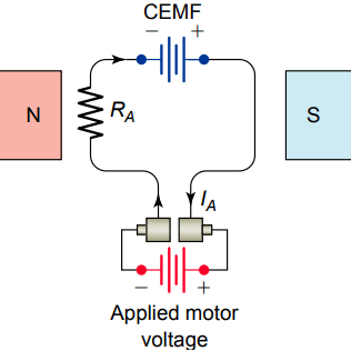
The overall effect of the CEMF is that this voltage will be subtracted from the terminal voltage of the motor so that the armature motor winding will see a smaller voltage potential.
Counter EMF is equal to the applied voltage minus the armature circuit IARA drop. The armature current, according to Ohm’s law, is equal to:
IA = (VMTR – CEMF) ÷ RA
Where IA = armature current,
VMTR = motor terminal voltage,
CEMF = counter electromotive force,
RA = armature-circuit resistance.
Counter EMF is directly proportional to the speed of the armature and the field strength. That is, the counter EMF increases or decreases if the speed is increased or decreased, respectively. The same is true if the field strength is increased or decreased.
At the moment a motor starts, the armature is not rotating, so there is no CEMF generated in the armature. Full line voltage is applied across the armature, and it draws a relatively large amount of current. At this point, the only factor limiting current through the armature is the relatively low resistance of the windings.
As the motor picks up speed, a counter electromotive force is generated in the armature, which opposes the applied terminal voltage and quickly reduces the amount of armature current.
When a motor reaches its full no-load speed, it is designed to be generating a CEMF nearly equal to the applied line voltage. Only enough current can flow to maintain this speed.
Significance of CEMF in DC Motor
When no load is applied to the motor, very small torque is required by it, which is necessary to overcome the friction and windage losses. Hence motor draws a very small armature current. Therefore, the difference between applied voltage and CEMF is very small.
But when we start loading the motor, this decreases the speed of the armature. This results in a fall in CEMF. This reduced CEMF causes a larger current to flow through the armature winding and a larger current produces increased driving torque.
Thus, the motor produces larger driving torque as it slows down. So motor will start running at the speed at which the armature current is just sufficient to produce the required torque by the load.
On the other hand, when the load on the motor is reduced, the speed of the armature increases due to excess driving torque. This increases the CEMF which results in decreased armature current. In this way CEMF in a DC motor regulates the flow of armature current according to the load requirement automatically.
Armature Reaction in DC Motors
The magnetic field produced by current flow through the armature conductors distorts and weakens the flux coming from the main field poles. This distortion and field weakening of the stator field of the motor is known as the armature reaction.
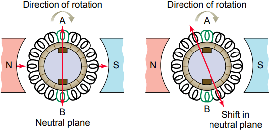
Figure 4 shows the position of the neutral plane under no-load and loaded motor operating conditions. As segment after segment of the rotating commutator passes under a brush, the brush short-circuits coil after coil in the armature.
Note that armature coils A and B are positioned relative to the brushes so that at the instant each is short-circuited, it is moving parallel to the main field so that there is no voltage induced in them at this point.
When operating under loaded conditions, due to armature reaction, the neutral plane is shifted backward, opposing the direction of rotation. As a result armature reaction affects motor operation by:
- Shifting the neutral plane in a direction opposite to the direction of rotation of the armature.
- Reducing motor torque as a result of the weakening of the magnetic field.
- Arcing at the brushes due to short-circuiting of the voltage being induced in the coils undergoing commutation.
- When the load on the motor fluctuates, the neutral plane shifts back and forth between no-load and full-load positions.
For small DC motors, the brushes are set in an intermediate position to produce acceptable commutation at all loads.
In larger DC motors, interpoles (also called commutating poles) are placed between the main field poles, as illustrated in Figure 5, to minimize the effects of armature reaction.
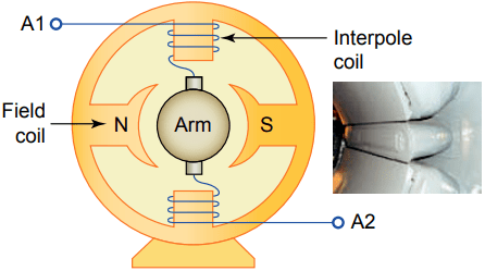
These narrow poles have a few turns of larger-gauge wire connected in series with the armature. The strength of the interpole field varies with the armature current.
The magnetic field generated by the interpoles is designed to be equal to and opposite that produced by the armature reaction for all values of load current and improves commutation.
Thanks for reading about “working principle of DC motor”.