Hi friends, in this article, I am talking about thermal overload relay working principle and its function in a DOL starter. I hope you will find this article informative and helpful.
A thermal overload relay works on the heat produced by the excessive overload current. The heat produced by the overload current is utilized to trip the motor circuit. These are mostly used for protection of low-voltage squirrel cage induction motors or DC motors of lower output rating.
The function of a thermal overload relay, used in motor starter circuits is to prevent the motor from drawing excessive current which is harmful to motor insulation.
It is connected either directly to motor lines or indirectly through current transformers. It de-energies the starter and stops the motor when excessive current is drawn.
Thermal Overload Relay Working Principle
Whenever the motor is overloaded, it will draw more current from the line and will be heated up gradually. The overload relay is intended to protect the motor against sustained overloads.
The overload relay is installed on motor control circuit to make a contact in the trip circuit or mechanically operate the trip bar thus shutting down the motor in the event of excessive load.
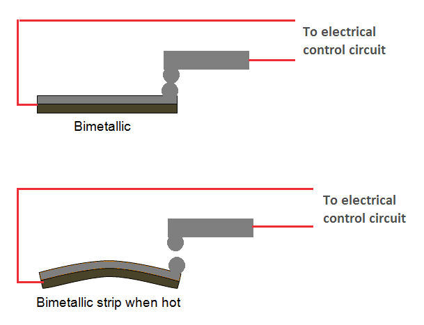
It consists bimetallic strips. The heat produced by the overload current is utilized to heat the bimetallic strips.
Under normal operating condition the strip remains straight but under the action of fault current the strip is heated and bent and the relay contacts get separated which de-energizes the motor control circuit.
The force required to bend the bimetallic strips can be adjusted by an adjuster. In other words, it can be adjusted to operate at different overload currents.
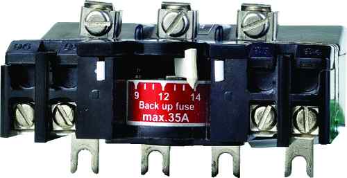
The thermal overload relay does not provide short circuit protection as it takes sufficient time to open the contacts. Therefore, this type of relay is used in conjunction with fuses to provide overload and short circuit protection to the circuit.
These relays have inverse time characteristics i.e. the tripping time becomes less as the over load and hence current increases. These are rated in trip class. The trip class specifies the period of time it will take to operate in an overload condition. The most common classes are 5, 10, 20 & 30. Class 30, 20, 10 and 5 overload relays will trip within 30, 20, 10 and 5 seconds respectively at 600% of motor full load amps.
Function of Overload Relay in DOL Starter
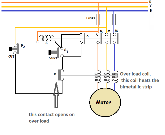
The circuit diagram for a DOL starter for a three-phase induction motor is shown in Figure. The starter essentially consists of a set of ‘start’ and ‘stop’ push buttons with associated contacts, overload and under voltage protective devices.
The start push button (S1, usually green colored) is a momentary contact switch that is held normally open by a spring. The stop push button (S2, usually red colored) is a momentary contact switch that is held normally closed by a spring. The operation is as follows.
When the start push-button S1 is pressed, the operating coil ‘C’ ( or the main contactor) get energized through the overload contact ‘D’ (normally closed). This closes the three main contacts ‘M’ that connect the motor to the supply. At the same time, the auxiliary contact ‘A’ is also closed.
When the auxiliary contact is closed, a new circuit is established through the stop push button, auxiliary contact and operating coil ‘C’. Since the operating circuit is now maintained by auxiliary contact, the motor keeps on running even after releasing the start push button.
If the supply fails or line voltage drops below a certain value, the main contacts and the auxiliary contact are opened. Upon return of the supply, the contactor cannot close until the start button is pressed again.
When the motor is overloaded, it draws current more than its normal operating current. This overload current heats the bimetallic strip of the thermal overload relay.
Now due to this heat, bimetallic strip starts bending. After some time, it bends sufficiently and motor control circuit opens at point ‘D’ (the point is shown in Figure). It disconnects the operating coil from the supply. As a result, the motor stops.
Thanks for reading about thermal overload relay working principle.
Three Phase Induction Motor | All Posts
- Three Phase Induction Motor Construction
- Rotating Magnetic Field in Three Phase Induction Motor
- Three Phase Induction Motor Working Principle
- Induction Motor Slip
- Torque Formula for Induction Motor
- Torque Slip Characteristics of Induction Motor
- Losses in Induction Motor
- Induction Motor Tests
- Starting Methods of Induction Motor
- Double Squirrel Cage Induction Motor
- Speed Control of 3 Phase Induction Motor
- What is a variable frequency drive?
- Autotransformer Starter Working Principle
- Induction Motor Equivalent Circuit
- Linear Induction Motor Working | Applications
© https://www.yourelectricalguide.com/ thermal overload relay working principle.