A dynamometer type wattmeter is basically a moving coil instrument. But in this case, the operating field is produced by the fixed coil instead of a permanent magnet. A wattmeter in which fixed coils produce the operating field is known as a dynamometer type wattmeter.
The dynamometer type wattmeters are very significant because we use them for power measurement in AC circuits very commonly.
Construction and Working of Dynamometer Type Wattmeter
In these wattmeters, the field produced by the current-carrying moving coil tries to come in line with the field produced by the current-carrying fixed coil, and a deflecting torque is exerted on the moving system. As a result, deflection takes place in the pointer.
Construction of Dynamometer Type Wattmeter
A dynamometer type wattmeter primarily consists of two coils called fixed coil and moving coil. The fixed coil is splitted into two equal parts, which are placed parallel to each other. The two fixed coils are air-cored to avoid hysteresis effects when used on AC.
The fixed coil is connected in series with the load and carries the circuit current. It is, therefore, called the current coil. Since current coils carry full load current, so these are made up of thick wire. And current flow through them is high, so few turns are sufficient to produce the desired magnetic field.
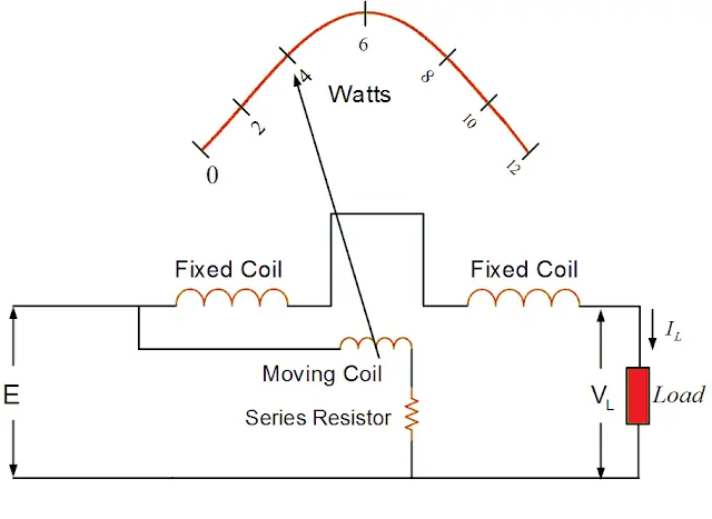
Generally, a high resistance is connected in series with the moving coil to limit the current through it. By limiting the current, the moving coil is made lightweight, which in turn increases the sensitivity of the instrument.
The springs provide the controlling torque. They also serve the additional purpose of leading the current into and out of the moving coil. Air friction damping is employed in such instruments.
Its current coil is connected in series with the load, carries the load current, and the potential coil, connected in parallel with the load, carries the current proportional to the voltage across the load.
Working of Dynamometer Type Wattmeter
The fixed coil produces a field Fm, and the moving coil creates a field Fr. The field Fr tries to come in line with the main field Fm, which provides a deflecting torque on the moving coil. Thus, the pointer attached to the spindle of the moving coil deflects. This deflection is controlled by the controlling torque produced by the springs.
Advantages of Dynamometer Type Wattmeter
- It can be used both on AC and DC circuits.
- It has a uniform scale.
- We can obtain a high degree of accuracy through careful design.
Disadvantages of Dynamometer Type Wattmeter
- At low power factors, the inductance of the potential coil causes serious errors.
- The reading of the instrument may be affected by stray fields acting on the moving coil. To prevent it, magnetic shielding is provided by enclosing the instrument in an iron case.
Errors in Dynamometer Type Wattmeter
The following are severe errors in this type of wattmeter:
1. Error due to potential coil inductance: The inductance of the potential coil is liable to cause an error in the reading of the wattmeter. Because of this error, the wattmeter gives a high reading on the lagging power factor and low reading on the leading power factor.
The high non-inductive resistance connected in series with the coil swamps the phasing effect of the potential coil inductance.
2. Error due to power loss in the potential coil or current coil: Another possible error in the indicated power may be due to some voltage drop in the current coil or the current taken by the potential coil.
We can overcome this defect by using an additional compensating winding. This winding is connected in series with the potential coil and so placed that it produces a field in the opposite direction to that of the current coils.
3. Error due to eddy currents: The alternating field of fixed or current coil induces eddy currents in the solid metal parts which set up their own magnetic field. This alters the magnitude and phase of the magnetic field, causing deflection.
Thus an error is introduced in the instrument reading. To reduce this error, the solid metal parts are placed as far away as possible from the current coil.
4. Error due to the stray magnetic field: The dynamometer type wattmeter has a relatively weak operating field; therefore, stray fields affect the reading of this instrument considerably and cause serious errors.
Hence, this type of instrument must be shielded against stray magnetic fields try using iron cases or providing thin iron shields over the working parts.
Range
Current circuit:- 0.25A – I00 A without employing CTs.
Potential circuit:- 5 V – 750 V without using PTs.
Deflecting Torque is Proportional to Power | Proof
In case of DC circuit:
Let,
V = Voltage across the load
I = Load current
Current through the fixed coil, I1 = I
Current through the moving coil, I2 α V
Since coils are air-cored, the flux density produced by the fixed coil is directly proportional to the current I1, i.e.
B α I1
The current-carrying moving coil is placed in the flux density produced by the fixed coil. Therefore, the deflecting torque, Td α BI2
or Td α I1I2
Td α IV
Td α Power
Hence, the deflection shown by the wattmeter is proportional to the power consumed in the circuit.
In the case of AC circuit:
Let,
v = instantaneous voltage across the load
i = instantaneous current through the load,
Cos φ = power factor of the load (lagging).
Now, v = Vm sinθ
i = Im sin (θ – φ)
The instantaneous value of current through the fixed coil, i1 = i
The instantaneous value of current through moving coil, i2 α v
Instantaneous deflecting torque α i2i
or Instantaneous deflecting torque α vi
Due to the inertia of the moving system, the pointer cannot follow the rapid changes in the instantaneous power. Hence the deflection will be proportional to the average torque and the wattmeter will show the average power consumption.
Therefore, average deflecting torque, Td α average of vi over a cycle.

Hence, the deflecting torque is proportional to the true power consumed in the circuit.
The controlling torque is provided by the springs. Therefore, Td α θ (where θ is deflection).
In a steady position of deflection,
Td = Tc
Power α θ
or θ α Power
Since deflection is proportional to the power to be measured (consumed by the load), therefore, dynamometer type wattmeter has a uniform scale.
Thanks for reading about the “construction and working of dynamometer type wattmeter”.
Related Posts
- Construction and Working of Moving Iron Instruments
- Construction and Working of Dynamometer Type Wattmeter
- Construction and Working of Megger
- Construction and Working of Megger Earth Tester
- Construction and Working of Power Factor Meter
- Construction and Working of Resonance Type Frequency Meter
- Construction and Working of Analog Frequency Meter
- Construction and Working of Thermocouple Instruments
- Construction and Working of Lux Meter
- Construction and Working of Electrostatic Voltmeter