All electrical appliances and industrial equipment consume power at a lagging power factor. The power factor of industrial and commercial installations tends to be low, usually ranging between 0.60 – 0.75 only. The overall power factor of any installation is likely to be below 0.7 unless corrective measures are adopted to improve it.
Due to various disadvantages of low power factor, the power supply companies insist on a power factor of 0.8 or above for industrial installations. To improve the power factor of an installation generally a capacitor bank is used. The power factor improvement using a capacitor bank is very common in an industrial installation.
Power Factor Correction Methods
There are many power factor correction methods. Some of the more common approaches are as follows:
- Addition of power factor correcting capacitors
- Addition of power factor correcting inductors
- Frequency manipulation
The power factor correction method chosen depends on the composition or design of the AC system.
In general, if the power factor is less than “1,” or 100%, due to the predominance of inductive reactance, XL, capacitance, or capacitive reactance, XC, must be added in series or shunt to raise the power factor closer to 100%.
The frequency manipulation method is applicable when, in addition to resistance, both inductive and capacitive reactances are present.
When the power factor is less than 100% due to the dominance of capacitance in an AC electrical system, inductive reactance may be introduced into the circuit to offset the capacitive reactance and improve the system’s power factor.
Power Factor Correction by Capacitors
Since power factor correcting capacitors, essentially, impact the AC circuits or systems through the addition of capacitive reactance XC, or ZC = – jXC, their addition to a predominantly inductive circuit yields different results depending upon whether they are connected in series with the load or parallel (or shunt).
A comprehensive discussion on the distinction between the addition of power factor correcting capacitors in parallel versus series is beyond the scope of this text.
Recognizing the fact that the difference in parallel versus series addition of capacitors is mainly due to the difference in parallel versus series addition of impedances, in general, should suffice.
Another side benefit of the use of a series capacitor is that they can reduce voltage drop, especially in motor starting situations and other high impulse loads. This can be attributed to the fact that capacitors don’t permit instantaneous drop or rise in voltage.
Power factor correcting capacitors can also be viewed as devices used to reduce the current in power systems. Capacitors do so by providing a leading current to loads that require a lagging current. In other words, capacitors provide “off-setting” current for inductive loads.
The investment in power factor equipment is relatively high as the p.f. approaches to unity because capacitors of much larger rating are required for bringing about the same improvement in p.f. when it is near unity than when it is low.
In actual practice, it is quite economical to work with an average p.f. of 0.92 – 0.95, as the advantages accruing from higher p.f. are counter balanced by the additional investment in capacitors.
Capacitance Required for Power Factor Improvement
There are multiple approaches for the assessment of capacitance required for specific improvement of power factor. One method relies on the knowledge of existing and desired reactive powers, Q1 and Q2, respectively; the operating voltage and the frequency. The formula for determination of the required per phase capacitance is as follows:
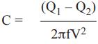
Where, C = Capacitance, in Farads, required to reduce the reactive power from Q1 to Q2 per phase.
Q1 = Initial, higher, reactive power, in VARs per phase.
Q2 = Improved, lower, reactive power, in VARs, per phase.
V = Voltage, in Volts.
f = Frequency, in Hz.
An electrical engineer may use the above equation to determine the capacitance required to improve the power factor, by a specific amount, instead of the apparent power (S) reduction approach.
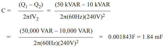
Example: A chilled water pump motor is drawing a reactive power, Q1, of 50 kVARs. If we want to improve the reactive power of the motor branch circuit to Q2 of 10 kVARs. Calculate the amount of capacitance that must be added, per phase, to achieve the objective. The branch circuit is operating at 240 VRMS. The system frequency is 60 Hz.
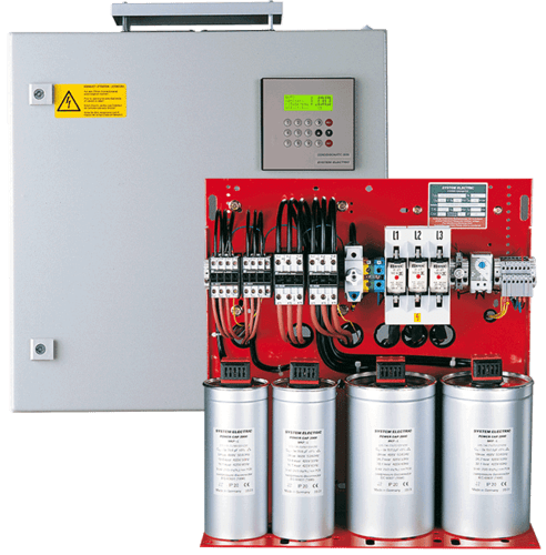
Automatic Switching PF Correcting Capacitor System
Imagine a plant where a 500 HP, air compressor is installed. The 500 HP rating of the air compressor is premised on the size of the motor. In other words, the 500 hp rating, in most cases would be real power (P) delivered by the motor to the compressor.
However, motors add inductive reactance to the electrical system. So, the branch circuit the motor pertains to, in this facility, would have a non-unity, or less than 100% power factor, say 80%. Sizeable loads, such as large air compressors, therefore, degrade the aggregate power factor of the entire electrical system.
On new installations, such as the one being considered here, degradation of power factor can be prevented by including automatic switching power factor correcting capacitor banks.
Automatic switching power factor correcting capacitor banks constitute a more optimal and effective approach for automatic introduction and removal of capacitance to maintain the system power factor at an optimal level.
The controls in an automated power factor correcting system connect or disconnect capacitors as the inductive load appears and disappears from the overall electrical circuit.
This ensures that the power factor correcting capacitors—and the associated capacitive reactance—drop out of the circuit when the compressor motor load (and associated inductive reactance) switches off.
If the power factor capacitors were to stay connected to the compressor motor branch circuit when the motor is off, the circuit would become predominantly capacitive, as XC would exceed XL, resulting in a low leading power factor.
In other words, if the capacitor bank is not disconnected when the compressor-based inductive reactance, XL, drops out, it would result in a capacitive reactance “overdose.”
The leading power factor creates the same problems as that of the lagging power factor, moreover, there is a possibility of a dangerous rise in voltage due to over-compensation.
In large installations, where the capacitors are connected in large groups, there is always a possibility of over-compensation on light loads. Therefore, where the load does not follow any regular pattern, automatic control of capacitors becomes necessary. Generally, APFC (Automatic Power Factor Control) panels are used in industries to control the power factor. In these panels, capacitors are connected and disconnected automatically with the help of APFC relay and capacitor duty contactors (CDC).
The application of power factor correcting capacitors should be preceded by proper analysis and design. Improper application of power factor correcting capacitors can damage the electrical system.
Improper application of power factor correcting capacitors can cause fuses to blow and can amplify system harmonics. After installation, capacitor banks must be included in the facility’s Preventive Maintenance Program. Loose connections and inherent defects, when ignored, can lead to unanticipated failures, faults, downtimes, and arc flash hazards.
A higher power factor means lower apparent power, S (in kVA), demanded and lower “unproductive” current in the electrical system. This “unproductive” current is wasted, as heat, as it flows through conductors, protective devices, power monitoring devices, transformers, and loads.
As we know, in general, the operation of equipment above normal temperatures results in shortening of the life of equipment. Therefore, improving the power factor not only results in improved energy efficiency but also extends service life, and reduces the maintenance cost of equipment.
If inductive reactance (XL, in Ω) and reactive power (Q, in VARs) are encountered through a distribution transformer, the application of PF capacitor is recommended at the distribution bus feeding the transformer.
When the inductive reactance (XL, in Ω) and reactive power (Q, in VARs) are contributed by large motors, the greatest PF corrective effect and energy loss reduction is realized when the capacitors are installed at each motor load (on line side), or between the motor starters and the motors.
However, the initial cost for some small banks of capacitors would tend to be higher than the initial cost of a single, large, bank of capacitors, catering to several motor loads. In such cases, the higher initial cost must be weighed against gains in energy cost and PF correction benefits.
Systems that experience large load swings, throughout the day or month, are good candidates for automatic switching correction systems.
Power Factor Correction by Inductor
If the power factor is less than “1” due to the predominance of capacitance or capacitive reactance, XC, inductance or inductive reactance, XL, must be added in series or shunt to raise the power factor closer to 100%.
In some AC electrical systems, such as the power transmission lines, the total impedance as seen from the utility side is indeed predominantly capacitive. In such cases, inductance must be added to improve the power factor.
Power Factor Correction by Frequency Manipulation
The frequency manipulation method pertains to AC electrical systems where both inductive and capacitive reactances are present, in addition to resistance. The power factor of such a system, peaks to the maximum value of unity, or 100%, at the resonance frequency. So we can control the power factor by changing the frequency of the system.
The frequency method for correcting power factor is feasible only in circumstances where the electrical frequency can be varied through the use of electromechanical systems such as electrical power generators, or via electronic variable frequency drives.
Example: An industrial consumer is operating 3-phase, 10 KW induction motor at a lagging p.f. of 0.8 and a source voltage of 400 Vrms. He wishes to raise the p.f. to 0.95 lagging.
Solution: Motor input P = 10 KW = 10000 W
Initial power factor (cos ø1) = 0.8 (lagging)
ø1 = cos-1 0.8 = 36.87o
Required power factor (cos ø2) = 0.95 (lagging)
ø2 = cos-1 95 = 18.195o
VAR rating of required capacitor will be
= P(tan ø1 – tan ø2)
= 10000(0.75 – 0.3287) = 4210.3 VAR = 4.21 kVAR
Thanks for reading about “power factor correction methods.”