Construction, Classification & Advantages of Cables
The transmission and distribution of electrical power can be done with the help of overhead transmission lines or by underground cables. It has been mentioned that in thickly populated areas like towns and cities, the use of overhead lines is not practicable. In such cases, electrical energy is transmitted and distributed with the help of underground cables.
In its basic form, an underground cable is a conductor provided with proper insulation. As the voltage level increases, the cost of the insulation increases rapidly and thus the use of underground cables is restricted to low and medium voltage distribution.
Comparison of Underground Cables and Overhead Lines
Compared to overhead lines, the underground cables have the following advantages:-
- It ensures non-interrupted continuity of supply. The possible supply interruptions due to lighting, storms, and other weather conditions are eliminated because of underground cables.
- It requires less maintenance.
- The accidents caused by the breakage of overhead line conductors are eliminated due to the use of underground cables.
- The voltage drop in the underground cables is less.
- The life of underground cables is long compared to overhead lines.
- The beauty of cities and towns is get maintained due to the underground network of cables.
- The overhead lines use bare conductors which is unsafe in thickly populated areas. Hence from the safety point of view, the underground cables are more advantageous.
The only drawbacks of underground cables are the extremely high initial cost and insulation problems at high voltages. In India, the big cities have adopted the system of underground cables for transmission and distribution.
Thus the use of underground cables is mainly for the distribution of electrical power at low and medium voltages. Its use is almost compulsory in the locations where use of overhead lines is not practicable due to safety reasons such as congested urban areas, crossing of wide roads, near gas plants and refineries, near substations, etc.
Still, the overhead lines also have some advantages compared to the underground cables which are:-
- Long-distance transmission is possible by the overhead lines.
- The conductor in overhead lines is less expensive.
- The size of the conductor in overhead lines is less than in underground cables due to good heat dissipation in overhead lines.
- The insulation cost is very low as the air itself acts as an insulation between the conductors. The gas or oil is not required for overhead lines. For high voltage levels, spacing in the air can be easily adjusted in the case of overhead lines to obtain proper insulation.
- The erection cost is much less for the overhead lines. The underground cable laying is complicated.
Depending on the situation and the requirements, the underground or overhead transmission system can be used.
Requirements of the Cables
An underground cable can be defined as a group of individually insulated one or more conductors which is put together and finally provided with several layers of insulation to give proper mechanical support.
The conductors used in the cables are usually aluminium or annealed copper while the insulation is commonly PVC or other chemical compositions. Many types of cables are available depending upon the nature of conductors, number of conductors, types of insulation used, etc. The basic requirements of the cables are:-
- The size of the conductor used must be such that it should carry the specified load without overheating and keeping the voltage drop well within the permissible limits.
- At the voltage level for which cables are designed, the insulation thickness must be proper to provide a high degree of safety and reliability.
- The cables must be surrounded by some layers of additional insulation to give proper mechanical strength and protection. Thus the cables can withstand rough use at the time of laying them.
- The materials used in the manufacturing of cables must be such that there is complete chemical and physical stability throughout.
General Construction of a Cable
The Fig. 1 shows the general construction of a cable. The cable shown is a single-conductor underground cable. Its various parts are,
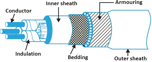
1. Conductor or core: This section consists of a single conductor or more than one conductor. The conductors are also called cores. A cable with three conductors is called a three-core cable. The conductors used are aluminum or annealed copper. The conductors are stranded conductors to provide flexibility to the cable.
2. Insulation: Each conductor or core is covered by insulation of proper thickness. The commonly used materials are varnished cambric, vulcanized bitumen and impregnated paper.
3. Metallic sheath: The insulated conductors are covered by a lead sheath or aluminum sheath. This provides mechanical protection but mainly restricts moisture and other gases from reaching the insulation.
4. Bedding: The metallic sheath is covered by another layer called bedding. The bedding consists of paper tape compounded with a fibrous material like jute strands or hessian tape. The purpose of bedding is to protect the metallic sheath from corrosion and mechanical injury resulting from armoring.
5. Armouring: This layer consists of layers of galvanized steel wires which protect the cable from mechanical injury.
6. Serving: The last layer above the armouring is serving. It is a layer of fibrous material like jute cloth that protects the armouring from atmospheric conditions.
Classification of Cables Based on Voltage
Classification of cables can be done in two ways according to
- based on insulating material used in their manufacture,
- based on the voltage for which they are manufactured.
However, the classification of cables based on voltage is more common, according to which they can be divided into the following categories:
- Low-tension cables — up to 1000 V
- High-tension cables — the operating voltage of high-tension cables is up to 11000 V
- Super-tension cables — the operating voltage of super tension cable is from 22 kV to 33 kV
- Extra high-tension cables — from 33 kV to 66 kV
- Extra super voltage cables — beyond 132 kV
Also, electrical cable classification can be done based on their construction as under:
- Belted cables — up to 22 kV
- Screened cables — from 22 kV to 66 kV
- Pressure cables — beyond 66 kV
Let us see the constructional features of these types of three-core cables.
Belted Cables
As mentioned earlier, these are used for voltage levels up to 24kV. The construction of the belted cable is shown in the Fig. 2
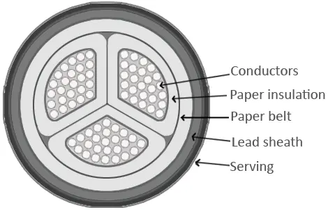
The cores are not circular. The cores are insulated from each other by the use of impregnated paper. The three cores are grouped and belted with the help of a paper belt. The gaps are filled with fibrous material like jute. This gives a circular cross-sectional shape to the cable.
The belt is covered with a lead sheath which protects the cable from moisture and also gives mechanical strength. The lead sheath is finally covered by jute-like fibrous compounded material.
The electric field in a single-core cable is radial while it is tangential in the case of three-core cables. Hence the insulation is subjected to tangential electrical stresses rather than radial ones. The paper has good radial strength but not tangential strength.
Similarly, paper resistance along the radius is much larger than resistance along the tangential path. The same is true for dielectric strength also. The fibrous material is also subjected to tangential electrical stresses, for which, the material is weak. Hence under high voltage cases, the cumulative effect of tangential electrical stresses is to form spaces inside the cable due to leakage currents.
Such air spaces formed inside the insulation are called void formation. This void formation is dangerous because, under high voltage, spaces are ionized which deteriorates the insulation and may lead to the breakdown of the insulation. Hence the belted cables are not used for the high voltage levels.
Another disadvantage of the belted cable is the large diameter of the paper belt. Due to this, wrinkles are formed and gaps may develop if the cable is bent. To overcome all these difficulties, the screened-type cables are used.
Screened Type Cables
These cables are used for the voltage levels of 22 kV and 33 kV. The two types of screened cables are
- H-type cables and
- S.L. type cables.
H-Type Cables: The cable is designed by M. Hochstadter and hence the name given to it is H-type cable. There is no paper belt in this type of cable. Each conductor in this cable is insulated with paper, covered with a metallic screen which is generally an aluminium foil. The construction is shown in Fig. 3.
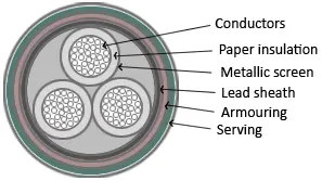
The metallic screen touches each other. Instead of a paper belt, the three cores are wrapped with a conducting belt which is usually copper woven fabric tape. Then there is lead sheath. The conducting belt is in electrical contact with the metallic screen and lead sheath. After the lead sheath, there are layers of bedding, armouring, and serving.
The metallic screen helps to completely impregnate the cable which avoids the possibility of formation of voids and spaces. The conducting belt, the three metallic screens, and the lead sheath are at earth potential, due to which electrical stresses are radial. This keeps the dielectric losses to minimum.
Another advantage of metallic screens is an increase in heat dissipation which reduces the sheath losses. Due to these advantages, the current carrying capacity of these cables increases. In special cases, the use of these cables can be extended up to the 66 kV level.
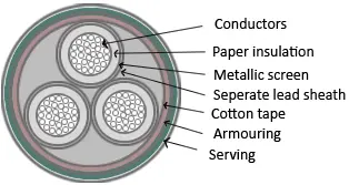
S.L. Cables: The name S.L. stands for Separate Lead Screened cable. In this cable, each core is insulated with an impregnated paper and each one is then covered by a separate lead sheath. Then there is a cotton tape covering the three cores together using a proper filler material. Then there are the layers of armouring and serving.
The difference between H-type and S.L. type cable is that in S.L. type a common lead sheath covering all three cores is absent while each core is provided with a separate lead sheath. This allows the bending of the cables as per the requirement. The construction of S.L. type cable is shown in Fig. 4. The three cores in this type of cable are as good as three separate single-core cables.
The various advantages of S.L. type cable are:-
- Due to individual lead sheath, core-to-core fault possibility gets minimized.
- The electrical stresses are radial.
- Due to the absence of an overall lead sheath, bending of cable is easy.
- The dielectric that gets subjected to electric stresses is paper which is homogeneous hence there is no possibility of formation of voids.
- Metal sheath increases heat dissipation which increases the current carrying capacity.
A combination of H-type and S.L. type cable called H.S.L. cable also can be used. The limitations of screened cables which are also called solid-type cables are:-
- It uses solid insulation only like paper. When the conductor temperature increases, the paper gets expanded. This eventually stretches the lead sheath.
- When the load on the cable decreases, it cools down and there is a contraction of the lead sheath. Due to this air may be drawn into the cable forming voids. This deteriorates the cable insulation.
- Moisture may be drawn in along with the air which deteriorates the dielectric strength of dielectric.
- Mechanical shock can cause voids. The breakdown strength of voids is much less than insulation. Hence voids can cause permanent damage to the cables.
Super Tension (S.T.) Cables
In solid-type cables, a separate arrangement for avoiding void formation and increasing dielectric strength is not provided. Hence those cables are used maximum of up to 66 kV level. The S.T. cables are intended for 132 kV to 275 kV voltage levels. In such cables, the following methods are specially used to eliminate the possibility of void formation :
- Instead of solid insulation, low-viscosity oils under pressure are used for impregnation. The channels are used for oil circulation and oil is always kept under pressure. The pressure eliminates, the formation of voids.
- Using inert gas at high pressure in between the lead sheath and dielectric.
Such cables using oil or gas under pressure are called pressure cables and are of two types,
- Oil-filled cables
- Gas pressure cables
Oil-Filled Cables
In the case of oil-filled cables, the channels or ducts are provided within or adjacent to the cores, through which oil under pressure is circulated. It consists of a concentrically stranded conductor but is built around a hollow cylindrical steel spiral core.
This hollow core acts as a channel for the oil. The oil channel is filled in a factory and the pressure is maintained in the oil by connecting the oil channel to the tanks which are placed at suitable distances along the path of the cable.
The oil pressure compresses the paper insulation, eliminating the possibility of the formation of voids. When the cable is heated, the oil expands but expanded oil is collected in the tank. When the cable is cooled, an extra oil is supplied by the tank to maintain the oil pressure.
In this type of cable, the oil channel is within the conductor, hence it is called single core conductor channel oil-filled cables. The other construction of the cable is similar to that of solid-type cables.
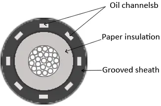
Another type of single-core oil-filled cable is the sheath channel oil-filled cable. In this type, the conductor is solid with paper insulation. While the oil ducts are provided between the dielectric and the lead sheath. The construction of the sheath channel oil-filled cable is shown in Fig. 5 The laying of such cables must be done very carefully.
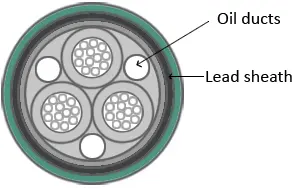
The three core oil-filled cables use the shielded type construction. The oil channels are located in the spaces which are normally occupied by the filler material. The three oil channels are of perforated metal ribbon tubing. All the channels are at Earth’s potential. The construction is shown in Fig. 6.
As the pressure tanks are required all along the route of these cables, the lengths of these cables are limited. The leakage of oil is another serious problem associated with these cables. Automatic signaling units are located to indicate the fall in oil pressure in any of the phases.
Advantages: The various advantages of oil-filled cables are:-
- The thickness of insulation required is less hence smaller in size and weight.
- The thermal resistance is less hence current carrying capacity is more.
- The possibility of voids is eliminated.
- The allowable temperature range is more than solid-type cables.
- Reduced possibility of earth fault. This is because, in case of any defect in the lead sheath, oil leakage starts, which can be noticed before an earth fault occurs.
- Perfect impregnation is possible.
Disadvantages: The disadvantages of oil-filled cables are:-
- The initial cost is very high.
- The long lengths are not possible.
- The oil leakage is a serious problem hence automatic signalling equipment is necessary.
- The laying of cable is difficult and must be done very carefully.
- Maintenance of the cables is also complicated.
Gas Pressure Cables
In the case of gas pressure cables, an inert gas like nitrogen at high pressure is introduced to lead sheath and dielectric. The pressure is about 12 to 15 atmospheres. Due to such a high pressure, there is a radial compression due to which the ionization is eliminated. The working power factors of such cables are also high.
The Fig. 7 shows the section of a gas pressure cable. The cable is triangular and installed in the steel pipe. The pipe is filled with nitrogen at 12 to 15 atmospheric pressure. The remaining construction is similar to that of solid-type cable but the thickness of the lead sheath is 75% of that of solid-type cable. There is no bedding or serving.
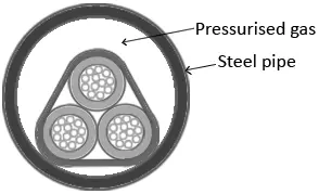
The triangular-shaped lead sheath acts as a pressure membrane. The shape reduces the weight and provides low thermal resistance. The high pressure creates radial compression to close any voids. The steel pipe is coated with paint to avoid corrosion.
During heating, the cable compound expands, and a sheath that acts as a membrane becomes circular in such a case. When the cable cools down the gas pressure acting via sheath forces the compound to come back to the noncircular normal shape. Due to good thermal characteristics, fire-quenching properties, and high dielectric strength, the gas SF6 is also used in such cables.
Advantages: The various advantages of gas pressure cables are:-
- Gas pressure cables can carry 1.5 times the normal load current and can withstand double the voltage. Hence such cables can be used for ultra-high voltage (UHV) levels.
- Maintenance cost is small.
- The nitrogen in the steel tube, helps in quenching any fire or flame.
- No reservoirs or tanks required.
- The power factor is improved.
- The steel tubes used make the cable laying easy.
- The ionization and possibility of voids is eliminated.
The only disadvantage of this type of cable is the very high initial cost.
Insulating Materials for Cables
Several layers of the various materials are used around the actual conductor in a cable. To isolate the conductor from the surroundings, the conductor is provided with insulation around it. Materials like paper, vulcanized rubber, PVC, etc. are used for providing such insulation.
The material to be used as insulation must have the following properties:-
- To prevent leakage current, its insulation resistance must be very high.
- To avoid electrical breakdown, its dielectric strength must be very high.
- To withstand mechanical injuries, it must be mechanically very strong.
- It should be flexible.
- It should be non-hygroscopic so that it will not absorb the moisture from the surroundings.
- It should be non-inflammable.
- It should be unaffected by acids and alkalies.
- It should be capable of withstanding high breakdown voltages.
- It should have high-temperature withstanding capability.
Practically it is not possible to have all these properties in a single material. Hence insulation material is selected depending upon the use of the cable and the quality of insulation required for it. Some changes are done at the time of design, depending upon the nature of the material selected.
For example, if the material is hygroscopic then a layer of waterproof covering is provided around it so that moisture can not reach the insulation. The main insulating materials which are in use are:-
- Poly Vinyl Chloride (PVC)
- Impregnated Paper
- Cross Linked Polythene
- Asbestos
Poly Vinyl Chloride (PVC): It is a thermoplastic synthetic compound. It is generally used to insulate the cables. It has a good dielectric strength (17 kV/mm) and a maximum continuous temperature rating of 75oC. The PVC cables can be bent to smaller radii which makes them particularly suitable for laying in industrial places.
Due to a high dielectric, mechanical strength, and exceptional moisture resistance, the PVC cables have almost completely replaced the paper and rubber-insulated cables in the range of up to 11 kV.
Impregnated Paper: Paper is a very good and cheap insulating material. But it is hygroscopic due to which its insulation properties get destroyed due to the ingress of moisture. To resolve this problem it is impregnated with some compounds such as paraffinic or naphthenic material.
The ends of paper-insulated cables should always be kept sealed to make them moisture-tight. Moisture can also enter through small pin-holes and crakes in the sheathing which may not be visible to the naked eye. Therefore, these cables are invariably metal-seathed to protect against ingress of moisture.
It has a high dielectric strength (40 – 50 kV/mm) and a continuous temperature rating of 80oC. It is used in high-voltage power cable manufacturing.
Cross-Linked Polyethylene: The cables using cross-linked polyethylene as the insulating material are known as XLPE cables.
- It has a high dielectric strength (20 – 40 kV/mm) and a continuous operating temperature rating of 90o
- It is non-inflammable, light in weight, flexible, mechanically strong, moisture absorption resistant, and has an extremely high melting point.
- These cables are directly laid on the soil bed and are used for voltages up to 33 kV.
Asbestos: Asbestos-insulated cables can withstand higher operating temperatures than paper, rubber, PVC, and varnished cambric cables. They are suitable for dry locations only as asbestos absorbs moisture. The operating temperature range is 100o – 200o depending upon the asbestos compound.
Glass, quartz, and silicon-rubber insulated cables are used where the operating temperature is above 105o.