Hi friends,
In this article, I am discussing the moving coil galvanometer working principle, its construction and conversion into voltmeter and ammeter. So let us start our topic.
A moving coil galvanometer is an easy and sensitive instrument to detect and measure electric current.
Galvanometer Working Principle
The working principle of galvanometer is based upon the fact that when electric current flows in a coil placed in a magnetic field, a deflecting torque acts upon the coil whose magnitude depends upon the strength of the current. From the measurement of the deflection of the coil, the strength of the current can be computed.
Moving-coil galvanometers are of two types:
- Suspended coil galvanometer and,
- Pivoted-coil or Weston galvanometer.
The principle and working of the two types of galvanometers are the same, only there is some difference in their constructions.
A suspended coil galvanometer can measure currents of the order of 10-9 A. In the suspended coil galvanometer the suspension strip is very delicate and may be broken by a small jerk. Therefore, the galvanometer cannot be taken from one place to another. This difficulty has been removed in the pivoted-coil galvanometers.
A pivoted-coil galvanometer is less sensitive than a suspended coil galvanometer but is more convenient and practical.
Construction of Galvanometer (Pivoted)
It consists of a coil having a large number of turns of fine insulated copper wire wound on an aluminum frame. The ends of the axle of the aluminum frame are inserted in two pivots so that the coil may rotate about the axle. At both ends of the coil, near the pivots, two springs are attached which produce a controlling torque on the moving system and connect the coil to the outer circuit.
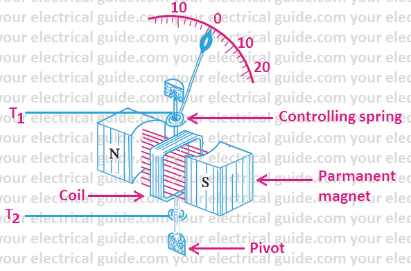
On both sides of the coil, there are pole-pieces of a permanent strong horseshoe magnet. The coil rotates in the magnetic field of these pole pieces.
To read the deflection of the coil, a pointer is attached to the coil which moves over a circular scale. The divisions on the scale are made at equal distances and the zero point is in the center. That is why no positive and negative signs are marked at the terminal screws of the galvanometer. It can measure currents up to 10-6 A.
Working of Galvanometer
When a galvanometer is connected to a current carrying circuit, a current flows in the coil of the galvanometer. Since the coil is suspended in a magnetic field, a deflecting torque acts upon it. Due to this torque, coil starts rotating from its position.
As the coil rotates, the controlling springs are twisted and an elastic restoring torque is developed in them and it opposes the rotation of the coil. This torque is proportional to the angle of rotation of the coil.
When the restoring torque (i.e. controlling torque) becomes equal to the deflecting torque, the coil rests in equilibrium position.
A galvanometer is used in electrical circuits to detect current, and in experiments to determine the null point.
If somehow a heavy current happens to flow into the coil of the galvanometer, then due to very large deflection the pointer of the galvanometer may strike the ‘stop pin’ and be broken, or coil of the galvanometer may burn due to excessive heat produced.
To save the galvanometer from these possible damages, a thick wire or strip of copper is connected in parallel with its coil. It is known as ‘shunt’. Its resistance is very small as compared to the resistance of the coil. Therefore, most part of the current goes through the shunt and only a very small part goes through the coil. Hence, there are no chances of damage to the coil or pointer.
Shunted-galvanometer is very useful for determining the null-point in experiments. First, the approximate position of the null-point is determined by using the shunted-galvanometer. At this stage, the current in the circuit is very feeble. Now the shunt is removed from the galvanometer so that full current goes through the galvanometer and accurate position of the null-point is determined.
Sensitivity of Galvanometer
A galvanometer is said to be sensitive if a small current passed through it produces a sufficiently large deflection. The sensitivity is of two types:
- current sensitivity and
- voltage sensitivity.
The current sensitivity of a galvanometer is defined as the deflection produced in the galvanometer when a unit current flows through it. The reverse of current sensitivity is known as ‘figure of merit’ of the galvanometer.
The voltage sensitivity of a galvanometer is defined as the deflection produced in the galvanometer when a unit voltage is applied across its coils.
Conversion of Galvanometer into Ammeter
Ammeter: An ammeter is an instrument used to measure currents in electrical circuits directly in amperes (A). The instrument measuring currents of the order of milli-ampere (mA) is called milli-ameter.
The ammeter is essentially a galvanometer which is inserted in the circuit in series so the whole of the current passes through it. The deflection produced in the ammeter is a measure of the current.
Since the coil of the ammeter has some resistance, so on inserting it in series of the circuit, the resistance of the circuit increases and the current in the circuit somewhat decreases. Therefore, the current read by ammeter is less than the actual current to be measured.
Hence it is necessary that the resistance of the ammeter be very small as compared to other resistances in the circuit.
A galvanometer cannot be used as an ammeter because it has appreciable resistance and it can measure only a limited current corresponding to the maximum deflection on its scale.
Conversion of Galvanometer into Ammeter
In practice, a galvanometer is converted into ammeter by connecting a low resistance in parallel with a galvanometer. This resistance is known as ‘shunt’. Its value depends upon the range requirement of the ammeter.
For the conversion of a galvanometer into an ammeter, a low resistance is connected across the galvanometer and hence an ammeter has much lower resistance than that of a galvanometer.
Let
G = resistance of galvanometer
S = resistance of shunt
Ig = full scale current of galvanometer
I = maximum current to be measured
Therefore, current through shunt = I – Ig
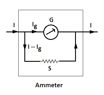
Since G and S are in parallel, the potential difference across them will be the same:
Ig*G = (I – Ig)*S ………..(i)
From this equation, S can be calculated.
Example: A galvanometer has a resistance of 15 Ω and meter shows full-scale deflection for a current of 4 mA. How will you convert the meter into an ammeter of range 0 to 6 A.
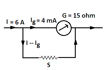
Solution: Here,
Galvanometer resistance, G = 15 Ω
Full scale current of galvanometer, Ig = 4 mA = 0.004 A
Maximum current to be measured, I = 6 A
Putting these values in equation Ig*G = (I – Ig)*S,
We get, 0.004*15 = (6 – 0.004)*S
or 0.06 = 5.996*S
or S = 0.06/5.996 = 0.010 ohms
Conversion of Galvanometer into Voltmeter
Voltmeter: A voltmeter is an instrument used to measure the potential difference between two points in electrical circuit directly in volt. The instrument measuring potential differences of the order of milli-volt (mV) is called milli-voltmeter.
It is also essentially a galvanometer which is connected in parallel across two points of the circuit of which potential difference is to be measured.
A part of the circuit current flows through the coil of the voltmeter and the p.d. between its ends equals the p.d. between those points. The deflection produced in the voltmeter is proportional to the current flowing through its coil and hence to the potential difference between its ends. Thus the deflection is a measure of potential difference.
Since the coil of the voltmeter has a finite resistance and draws some current, so on connecting it across two points, the p.d. between those points somewhat falls.
Therefore, the p.d. read by the voltmeter is slightly less than that the actual p.d. to be measured.
Hence, the resistance of the voltmeter should be very high as compared to any circuit resistor across which the voltmeter is connected. An ideal voltmeter has infinite resistance.
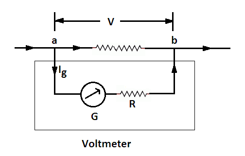
A galvanometer can be converted into voltmeter by connecting a resistor of high resistance in series with it. This resistance is known as ‘multiplier’. The value of multiplier depends upon the range requirement of the voltmeter.
For the conversion of a galvanometer into a voltmeter, a high resistance is connected in series with the galvanometer and hence the resistance of a voltmeter is very high as compared to that of a galvanometer.
Let
G = resistance of galvanometer coil
Ig = full-scale current of galvanometer
R = high resistance connected in series with galvanometer
V = maximum potential difference to be measured
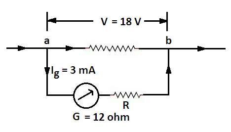
From the figure, it is clear that, Ig (G + R) = V
From this equation, we can find out the value of R.
Example: A galvanometer coil has resistance of 12 Ω and the meter shows full-scale deflection for a current of 3 mA. How will you convert the meter into a voltmeter of range of 0 to 18 V.
Solution: Here,
Resistance of galvanometer coil, G = 12 Ω
Full scale current of galvanometer, Ig = 3 mA = 0.003 A
Value of high resistance to be connected in series with galvanometer, R
Maximum potential difference to be measured, V = 18 V
Putting above data in the equation, Ig (G + R) = V
We get, 0.003 (12 + R) = 18
or 12 + R = 18/0.003 = 6000
or R = 6000 – 12 = 5988 Ω
Thanks for reading about “galvanometer working principle” and “working principle of galvanometer”.
Electrical Measuring Instruments | All Posts
- Deflecting, Controlling and Damping Torque
- Moving Iron Instrument Working
- Moving Coil Instrument Working
- Range Extension of Ammeters and Voltmeters
- Dynamometer Type Wattmeter Working
- Analog Multimeter Working Principle
- Working Principle of Megger
- Earth Megger Working Principle
- Power Factor Meter Working Principle
- Vibrating Reed Type Frequency Meter
- Analog Frequency Meter Working Principle
- Moving Coil Galvanometer Construction & Working.
- Thermocouple Instrument Working Principle
- Lux Meter Working Principle
© www.yourelectricalguide.com/ Moving coil galvanometer working principle.