In this system, a delta/star-connected transformer is used. Three wires are taken from the phases and the fourth wire (i.e. neutral wire) is taken from the star point. If the voltage of each phase conductor to neutral is V then line to line voltage between the phases will be √3V. The 3 phase 4 wire system is generally used for the secondary distribution.
3 Phase 4 Wire System
The power from generating stations is transmitted over long distances through transmission lines to various receiving stations. The power is then distributed to various sub-stations located at various places and localities. The voltage is ultimately stepped down to 400/230 volts i.e. 400 volts for bulk consumers and 230 volts for general domestic consumers.
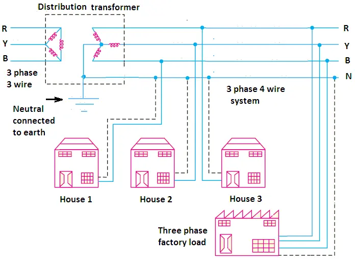
Windings of these distribution transformers are connected in the delta on the primary side and in the star on the secondary side. The voltage between any phase wire and neutral is 230 volts and between any two phase wire is 400 (√3 x 230 = 398.37) volts.
The supply to houses, small offices, shops other premises requiring small loads is taken from the distribution mains at 230 volts with the help of one phase and one neutral wire.
Where supply is to be given to a large establishment like hotels, offices, or hospitals the system of three phase four wire supply is adopted. It consists of three phase wires and a neutral.
Neutral Current in 3 Phase 4 Wire System
The function of neutral wire in the 3-phase 4-wire system is to serve as a return wire for the general domestic supply system. The neutral is paired with each of the single-phase loads. The potential of the neutral point can be very well understood from the following Figure.
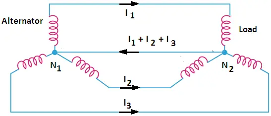
In the above diagram, the alternator is connected to the load. The neutral points in both the alternator and the load are joined together. The neutral wire serves as a common return to all three phases acting outward from N1.
Therefore, the total neutral current is the vector sum of the three line currents. Under balanced conditions, the vector sum is zero, and therefore, the neutral current is zero. In this case, there is no question of voltage drop along neutral and the potential of N2 is the same as that of N1.
This makes it clear that if the supply system is reverted to the three-phase three-wire system, the neutral conductor can be removed without any change in the potential of the distribution network. In that case, the potential of N2 will still be equal to that of N1. This is why, the main transmission network is three wire system.
The three-phase loads are balanced and do not contribute to neutral current therefore the neutral conductor can be removed.
However, balancing of load on every phase is difficult in the case of single-phase loads. Due to this imbalance, some neutral current always flows. Therefore, the neutral wire is very essential in this case.
Balancing of Phases in 3 Phase 4 Wire System
Balancing of phases means the distribution of single-phase lighting loads equally on 3-phase 4-wire supply line conductors so that the line currents on all the phases are approximately equal.
The difference in load will cause an out-of-balance current to flow through the neutral wire. The impedance of three conductors will be the same and unequal current flowing through them will give rise to unequal voltage drops with the possibility of the voltages at the loads being unbalanced. However, attaining absolutely equal distribution in such cases is not possible and as a result, a small current in the neutral may exist.
To obtain a fairly equal distribution of load in three-phase wires, the residential buildings should be connected sequentially, where three-phase supply is given to the large buildings such as hotels, schools, commercial buildings, etc., equal distribution of the load on all the phases must be the main objective.
The ‘balancing’ provides the most effective utilization of the generator and the transformer. For instance, a 100 kVA transformer can satisfactorily take a 33.3 kVA single-phase load on each of its phases. If it is connected to only one phase supply, it will then be overloaded.
Voltage between Neutral and Earth
Very little voltage between the neutral and the earth may exist as the neutral is solidly connected to the earth at the sub-station and it may rise if the earthing of the sub-station is not working properly.
Under faulty conditions, for instance, the fuse or the circuit breaker protecting the feeder does not trip in the case of an earth fault on one of the lines, the neutral may attain a much higher potential with respect to the earth.
Under such conditions, there will be heavy voltage drop across the sub-station earth due to fault current which may give quite severe electric shock.
Why is the Neutral Earthed?
The purpose of earthing of neutral is shown in Figure.
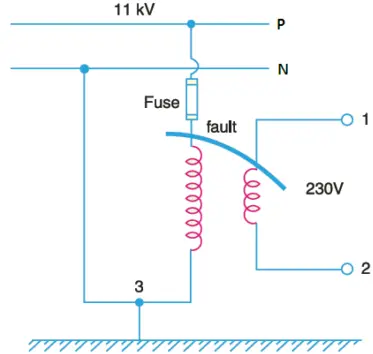
In Figure 3, an 11 kV / 230 V transformer is fed from an 11 kV line is shown. The secondary of this transformer is not earthed in this case.
If the insulation between HT and LT windings fails due to any reason, the 11 kV supply voltage will appear at the 230 V terminals of the transformer. It will be a very dangerous situation for both equipment connected to that line and the operator.
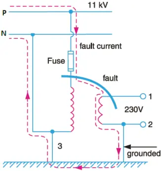
Now look at Figure 4, the secondary of the transformer is earthed in this case. If the 11 kV voltage appears at secondary terminals then excessive current will flow through the path shown in the Figure and the fuse will blow.
Hence the earthing of the neutral wire of a distribution transformer at the sub-station is very necessary from the safety point of view.
What Happens when Neutral is Disconnected
When the neutral wire in a 3-phase, 4-wire system is disconnected, the loads that are connected between any two line conductors and the neutral are get connected in series and the potential difference across the combined load becomes equal to the line voltage. The potential difference across each load is changed according to the rating of the load.
Illustration: The effect of disconnecting neutral wire in a 3-phase 4-wire system can be explained more clearly by the following illustration:
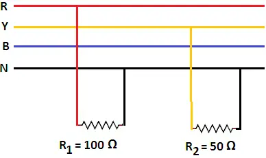
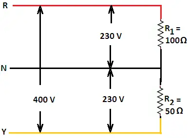
Suppose a resistance of 100 Ω is connected between the R-phase and neutral and a resistance of 50 Ω is connected between Y-phase and neutral as shown in Figure 5. The simplified diagram is shown in Figure 6.
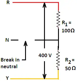
If the neutral wire is disconnected, the two loads R1 and R2 are get connected in series and the potential difference across them becomes equal to the line voltage i.e. 400 V.
Therefore, current through loads, I = VL/(R1 + R2)
= 400 /(100 + 50) = 2.67 A
Therefore, the potential difference across the resistance R1 = I*R1
= 2.67*100 = 267 V
Similarly, the potential difference across the resistance R2 = I*R2
= 2.67*50 = 133 V
It is clear from the above illustration that if the neutral wire is disconnected in a 3-phase 4-wire system the potential difference across the high resistive load is increased and the potential difference across the low resistive load is decreased. In this process, the voltage across the high resistive load may rise more than the designed value and may damage the high resistive load.
Very well explained.
Thank you so much.