A data acquisition system (DAQ) is a computerized system that collects data from the real world, converts it into the form of electrical signals, and does required processing on it for storage, and presentation on computers.
It acts as a bridge between the physical world and the digital realm. It captures physical quantities like temperature, pressure, light, or vibration and converts them into a digital format that computers can understand and analyze.
The complete system is controlled and operated by a software application. This software application is developed by using general-purpose high-level programming languages like C, C++, java, etc.
These systems are used in industrial and commercial fields. They are used for collecting, storing, and processing of data.
Data Acquisition System Block Diagram
Transducers: This is the frontline component, responsible for converting a physical quantity into an electrical signal. Examples include thermocouples for temperature, pressure transducers for pressure, and photodiodes for light. The most commonly used transducers are:
- RTDs, thermocouples, and thermistors for temperature measurements.
- Photosensors for light measurements.
- Strain gages, and piezoelectric transducers for force and pressure measurements.
- Microphone for sound measurements.
- Potentiometer, LVDT, and optical encoder for position and displacement measurements.
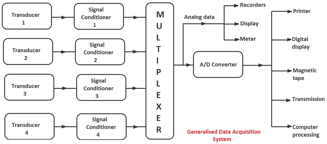
Signal Conditioner (Optional): The signal produced by the transducers may or may not be very suitable for our system to work properly. It may be very weak, very strong, or may have some noise.
To convert this signal into the most suitable form, amplification, and filtration are done respectively by signal conditioning unit. So the signal conditioning unit converts electrical signals in the most suitable form. The signal conditioner ensures the signal is suitable for the next stage.
Multiplexer (Optional): If you’re dealing with multiple sensors, a multiplexer acts like a traffic controller, rapidly switching between sensor signals and sending them one at a time to the next stage.
The multiplexer receives multiple analog inputs and provides a single output signal according to the requirements.
If a separate channel is used for each quantity, the cost of installation, maintenance, and periodic replacement becomes high. Therefore, a single channel is used which is shared by various quantities.
Analog-to-Digital Converter (ADC): The ADC converts the analog electrical signal from the sensor (voltage) into a digital signal (a series of 0s and 1s) that a computer can understand. The resolution (number of bits) of the ADC determines the accuracy of the digital representation.
After the conversion of data into digital form, it is displayed with the help of oscilloscopes, numerical displays, and panel meters to monitor the complete system.
Also, the data can be either permanently or temporarily stored or recorded according to the requirement. The data is recorded on optical, ultraviolet, stylus, or ink recorders for future use.
Data Logger/PC: This is where the digital data is stored and processed. It can be a dedicated data logger or a personal computer equipped with a DAQ interface card. The data logger can store the data for later analysis or transfer it to a PC for real-time monitoring and analysis.
Output/Display (Optional): The processed data can be displayed on a screen, recorded on a storage device, or transmitted for remote monitoring and analysis.
Objectives of Data Acquisition System
- It must collect the necessary data at the correct speed.
- It must use all the data efficiently to inform the operator about the state of the system.
- It must monitor the complete system operation to maintain online optimum and safe operations.
- It must be able to summarize and store data for the diagnosis of operation and record purposes.
- It must be flexible for future requirements.
- It must be reliable and not have a downtime of more than 0.1%.
- It must provide an effective communication system.
Basic Types of Data Acquisition Systems
Data acquisition systems (DAQ) can be classified into various categories depending on the specific criteria. Here’s a breakdown of two common ways to categorize DAQ systems:
By Signal Type
- Analog Data Acquisition Systems: These systems deal with continuous signals that can have any value within a specific range. They use analog-to-digital converters (ADCs) to transform these continuous signals into digital data for computer processing. Examples include temperature sensors, pressure gauges, and microphones.
- Digital Data Acquisition Systems: These systems work with signals that already exist in digital form, such as on/off signals or data from digital sensors. They handle tasks like acquiring, storing, and transmitting digital data. Examples include logic gates, encoders, and digital accelerometers.
By Form Factor
DAQ systems come in various shapes and sizes to suit different needs and applications. Here are some of the common form factors:
- Computer-connected DAQ Modules: These are compact and portable devices that connect to a computer via USB or other ports. They are ideal for basic data acquisition tasks on a single PC.
- Stand-alone Data Acquisition Systems (Portable): These are self-contained systems with built-in processors and data storage capabilities. They are suitable for field applications where a separate computer might not be available.
- Rack-mounting Data Acquisition Systems: These are large and powerful systems designed for complex applications that require handling numerous channels of data or high-speed data acquisition. They are typically installed in industrial control rooms or research labs.
Advantages of Data Acquisition Systems
Data acquisition systems (DAQ) offer a significant advantage over traditional methods of data collection by automating and streamlining the process. Here are some of the key benefits of using DAQ systems:
- Improved Efficiency and Reliability: DAQ systems remove the need for manual data collection, which can be slow, error-prone, and labor-intensive. By automating data collection, DAQ systems ensure consistent and reliable data streams, allowing for better monitoring and control of processes or experiments.
- Faster Problem Analysis and Resolution: With real-time data acquisition, DAQ systems provide immediate access to critical measurements. This allows for quicker identification of issues and faster decision-making to resolve problems before they escalate.
- Reduced Errors: DAQ systems minimize human error by automating data collection and reducing the need for manual data entry. This ensures the accuracy and integrity of the collected data.
- Improved Data Quality: DAQ systems can be configured to collect data at high speeds and with high precision. This improves the overall quality of the data and allows for more detailed analysis.
- Increased Productivity: By automating data collection and reducing manual tasks, DAQ systems free up personnel to focus on other important activities, leading to increased productivity.
- Cost Savings: While there’s an initial investment in DAQ systems, they can lead to cost savings in the long run. Reduced labor costs, improved process efficiency, and fewer errors can contribute to significant financial benefits.
- Better Decision Making: DAQ systems provide a wealth of data that can be used to gain insights into processes, identify trends, and make data-driven decisions. This can lead to improved product quality, process optimization, and better overall performance.
Overall, DAQ systems are valuable tools that can enhance data collection, analysis, and decision-making across various industries and applications.
Disadvantages of Data Acquisition Systems
Data acquisition systems (DAQ) are powerful tools, but they do come with some drawbacks to consider:
- Cost: Setting up a DAQ system can be expensive. The initial investment includes the cost of specialized hardware (sensors, DAQ modules), software, and potentially additional components like signal conditioning equipment.
- Complexity: DAQ systems can be intricate, especially for complex applications. Configuration, calibration, and maintenance may require expertise in both hardware and software to ensure proper operation and reliable data collection.
- Compatibility Issues: Integrating different sensors, hardware components, and software from various vendors can be challenging due to compatibility issues. This might necessitate additional research or technical support to ensure everything works seamlessly together.
- Limited Sensor Range: Not all sensors are compatible with every DAQ system. The specific types of sensors a system can handle will depend on its capabilities. Make sure the chosen DAQ system can accommodate the sensors you need for your application.
- Data Security: DAQ systems collect and store sensitive data. Implementing proper security measures is crucial to protect this data from breaches or unauthorized access.
- Power Dependence: Most DAQ systems rely on a constant power supply to function. In situations where power outages are a concern, consider using backup power solutions or portable DAQ systems for field applications.
- Potential for Downtime: Even with proper maintenance, DAQ systems can experience malfunctions or breakdowns. This can lead to downtime and data loss if not addressed promptly.
While these disadvantages exist, careful planning, selecting the right equipment for your needs, and proper system setup can help mitigate these drawbacks. DAQ systems offer significant advantages in many applications, and with an understanding of their limitations, you can make informed decisions about their implementation.
Applications of Data Acquisition System
Data acquisition systems (DAQ) are incredibly versatile tools used in a wide variety of applications. They essentially act as translators, taking physical world measurements from sensors and converting them into digital data that computers can understand. This data can then be analyzed, stored, and used to inform decisions and processes. Here are some of the common applications of DAQ systems:
- Industrial process control: In factories and manufacturing plants, DAQ systems are used to monitor and control various aspects of production lines. Sensors can track temperature, pressure, flow rate, and other parameters to ensure that processes are running efficiently and within specifications.
- Scientific research: Researchers in a wide range of fields rely on DAQ systems to collect data from experiments. For example, a biologist might use a DAQ system to measure the electrical activity of neurons, while an engineer might use one to track the strain on a bridge.
- Environmental monitoring: DAQ systems are essential for monitoring air and water quality. They can track levels of pollutants, greenhouse gases, and other environmental factors. This data is used to assess environmental health and develop regulations.
- Medical diagnosis: In hospitals, DAQ systems are used to collect vital sign data from patients. This data includes heart rate, blood pressure, and oxygen levels. Doctors use this information to diagnose and treat medical conditions.
- Building automation: DAQ systems are used in buildings to control heating, ventilation, and air conditioning (HVAC) systems. They can also be used to monitor energy consumption and security systems.
These are just a few examples of the many applications of DAQ systems. Their versatility makes them an essential tool in a wide range of industries and fields.
Additional Points
- DAQ systems can be designed for various sampling rates, depending on the speed of the phenomenon being measured. High-speed phenomena require faster sampling rates to capture rapid changes.
- DAQ systems come in various configurations with different functionalities and complexities. They can be standalone units or integrated with control systems for real-time feedback and process adjustments.
- By understanding these core components, you can grasp the essential workings of a data acquisition system, a crucial tool for scientific research, industrial monitoring, and various applications where capturing and analyzing real-world data is vital.
Good Information. Thank you for sharing. Proact, founded in 2001 and based in Bengaluru, is a leading force in high-tech industries like aerospace, aviation, electronics, defense, and more. Renowned for innovation and excellence, Proact offers tailored solutions to diverse challenges, making it a trusted partner for businesses. Explore cutting-edge services and products at https://www.proact-ims.com/ or contact us at +91 80 3542 9949 for collaboration and innovation opportunities. Elevate your projects with Proact’s expertise.