Hi friends,
In this article, I am discussing the radar working principle, block diagram and applications. So keep reading.
A radar which stands for “radio detection and ranging” is a method of detecting the presence and position of objects by reflected radio waves. The detected object is called target and the distance to the target is determined by measuring the time interval between transmission and reception of the reflected radar signal.
Radar Working Principle
Most radar sets employ pulse radar wherein the transmitter sends out short intense bursts or pulses of energy of about one micro second duration with a relatively long interval of several hundred micro-seconds between the successive pulses. When sufficient time has elapsed to permit the reception of the echoes from the most distant desired objects, the transmitter sends another short pulse and the cycle repeats.
The transmitting antenna also functions as the receiving antenna. The reflected signal after amplification of several million times is used to deflect the electron beam in a cathode ray tube. The echo picked up by the receiver strengthens or deflects the flow of electrons in the tube, causing a point of light to appear on the screen which remains visible by phosphorescent after-glow until fresh echoes are picked up on the next revolution of the scanning antenna.
The angular bearing to the target is determined by measuring the direction from which the reflected energy is received. It is expressed in two components; azimuth angle measured in the horizontal plane and elevation angle measured in a vertical plane. The indicator tube is arranged to directly display the target co-ordinates and distance.
Applications of Radar System
Radar is being increasingly used as a navigational aid in ships, airplanes, and automatic landing systems, and for weather and storm forecasts, etc. The angular beam width is determined by the radio frequency (wavelength) employed relative to the size of the reflecting surface of the radiator. The shorter the wavelength, the sharper the beam produced by a reflector of a given size. This is the principal reason for the use of micro-waves (1 to 10 cm wavelength) in radar operations.
Objects within a distance of about 300 m are not detectable by radar because of the minimum time of about two micro-seconds required before a pulse of one micro-second can be reflected and received.
The scanning pattern employed depends upon the intended service of the radar. For example, circular scanning (motion of the beam in azimuth in a circle around the horizon) is used in searching for low-flying aircraft and marine targets. Helical scanning covers the elevation angle as well as the azimuth and is used for the search of Air-borne targets.
Block Diagram of Radar System
The typical block diagram of radar system is shown in Figure. The essential elements of a radar system are:
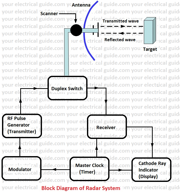
The timer device is used for coordinating the action of the transmitter, receiver, and indicator, to ensure synchronized operation.
The modulator is used to amplify pulses supplied by the timer to sufficient amplitude to operate the transmitter.
The transmitter is used to convert modulator pulses into RF pulses.
The antenna is used to radiate the transmitted pulse and receives the reflected signal over a sharply defined beam.
The scanner, an electro-mechanical system for moving the radiator or antenna to scan the space for targets scanner also generates signals (voltage or current) proportional to the azimuth and elevation components of the angular bearing of the beam for transmission to the indicator.
The receiver which amplifies and demodulates the received signal. The receiver used in the radar systems is generally of the superheterodyne type. The local oscillator of the receiver is ultra high-frequency triode for frequencies below 1000 Mc, and for higher frequencies, ‘reflex klystron’ is used as a local oscillator. The I.F. is generally in the range of 30 Mc which is further amplified in I.F. amplifiers.
The cathode ray indicators for displaying the echo signal and the target coordinates.
Duplex Switch or Transmit-Receive Switch (T/R Box): This may consist of an open spark gap across the transmission line or as is generally the case, an enclosed low-pressure T/R tube is used. This is placed in a cavity which steps up the voltage existing across the transmission line so that the gap will break down when the transmitted pulse appears across it. When the transmitted pulse is concluded, the ionization within the T/R tube clears up in about a micro-second, freeing the transmission system to carry the received signals to the receiver.
Radar Transmitter: It is essentially a device for converting modular pulse into RF energy. It is a self-excited oscillator, which for carrier frequencies below 500 Mc employs UHF triode, and for higher frequencies of the order of 1500 – 3,00,000 Mc/s special ultra-high-frequency tubes like magnetron and klystron are used.
The transmitter must generate pulses at the highest possible power for the pulse duration. The cathode of the transmitting tube is designed to be suitable for heavy emissions and the plate voltage is of the order of 10 – 25 KV. The R.F. energy is conveyed from the transmitter to the antenna and from the antenna to the receiver over co-axial cables or waveguides.
The co-axial cable consists of a hollow outer conductor within which a small conductor is supported on low-loss insulating beads or flexible solid dielectric (Polyethylene). With properly matched terminating impedances, such cables can carry peak power of the order of hundreds of kilowatts without developing an excessive voltage across the line.
Waveguide: The waveguide transmission line is a hollow conductor of rectangular or circular cross-section.
Indicators: The cathode-ray tubes used as indicators in radar systems take various forms depending upon the required presentation; the most widely used indicator being the plan-position indicator on a polar diagram. In this device, the cathode-ray spot is deflected radially outward from the center of the tube at a constant rate and the beam is intensified whenever a reflected signal appears.
Consequently, the range of the target is indicated by the distance from the center at which the spot appears. The polar angle on the indicator screen indicates the azimuth angle.
Auxiliary circuits for the cathode-ray tube include a high-voltage power supply and controls for adjusting the brightness and focus of the cathode-ray spot. The echo signal from the receiver is applied to the control grid (if positive) or cathode (if negative) of the electron gun of the indicator tube.
The deflection of the cathode-ray beam to indicate the target coordinates is produced in sweep circuits. The range sweep creates a voltage or current which increases linearly with time and then suddenly reverts to its initial value, i.e. it has saw-tooth shape when plotted against time. Each tooth of the wave starts simultaneously with the transmitted pulse and ends after sufficient time has elapsed to allow the echo to arrive from the farthest target.
The direction sweeps are similar, linear saw-tooth waves of current or voltage created by the motion of the scanner in azimuth and elevation.
Ultra-high Frequency Generators
It is not possible to generate the UHF waves which are used in radar, television, and point to point communication with conventional triode tubes because of the constructional limitations like clearance between grid and cathode which cannot be reduced below 15 microns. Special UHF generators as listed below are employed for the purpose.
- Disc-seal triode
- Cavity magnetron
- Reflex klystron.
Disc-seal Triode: In the disc seal triode, which functions similar to a conventional triode tube, the cathode, grid, and anode are constructed in the form of discs placed in parallel planes with very small spacing between the cathode and grid. The terminals of electrodes are in the form of discs extending through the glass envelope. The disc terminals from parts of two metal cavities which surround the tube and act as tuned circuits. Self-sustained oscillations are produced by connecting the grid cavity to the plate cavity by a coupling loop.
Cavity Magnetron: The cavity magnetron is widely used for generating RF power at frequencies of 1000 to 100,000 Mc. It is properly speaking, a diode since it consists of cylindrical cathode surrounded by an anode.
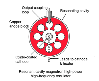
An even number of identical cylindrical cavities are cut in the body of the anode which serves as cavity resonators. Each resonator connects with the space between the cathode and anode through a slot.
The anode structure and oxide-coated cathode arranged axially in the center of the anode block are enclosed in a vacuum within a metal or glass envelope. An external permanent magnet provides the axial magnetic field. The permanent magnetic field with constant field strength functions as a virtual grid.
The natural period of these resonators is chosen at the value at which the magnetron is required to operate. A steady magnetic field of several thousand gauss is passed through the tube parallel to the axis of the cathode. The tube is activated by applying a high voltage (several thousand volts) between the anode and cathode.
This voltage causes electrons to leave the cathode surface and approach the anode, but in passing through the magnetic field, the electrons are forced to execute a spiral motion. Superimposed on this is an RF electric field across the slots, due to the oscillations within the cavities. As a result, the electrons are bunched along a radial line and the bunch rotates about the structure like the spokes of a wheel.
The electron bunch, passing the slots in the inner surface of the anode in the proper phase, gives up its energy and thus transfers power from D.C. power (applied to the anode) to RF power within the slots. The power is abstracted from one of the cavities by a coupling loop.
Thanks for reading about “radar working principle”.
Related Posts
- P N Junction Diode Theory | Working
- Characteristics of PN Junction Diode
- Working Principle of Rectifier
- Zener Diode Characteristics
- Zener Diode as Voltage Regulator
- JFET | Junction Field Effect Transistor Basics
- JFET Construction and Working
- Op Amp | Operational Amplifier Basics
- Transistor as a Switch
- Buck Converter Working
- Buck Boost Converter Working
- Astable & Monostable Operation of 555 Timer Chip
- Light Sensitive Devices
- Industrial Applications of Ultrasonic Waves
- Radar Working Principle
- Electrical Timer & Timer Charts
- RLC Parallel & RLC Series Circuit Resonance
- Types of Capacitors
© www.yourelectricalguide.com/ working principle of radar system.