Hi friends,
In this article, I am discussing the stepper motor working principle, its basics and applications. You will find it informative and interesting. So keep reading.
As the name implies, a stepper motor, within its operation range, and capability, starts, stops, reverses and moves through a predetermined stepping angle under commands from an electronic logic controller. In other words, a stepper motor is a device which converts digital pulses into precise angular movement.
Stepper Motor Working Principle
A stepper motor is a D.C. motor with field placed on the rotor in the form of permanent magnets with two, three or four sets of coils called phases, placed in the stator around the rotor. The windings are connected to an external logic driver which delivers voltage pulses to the windings sequentially. The motor responds to these pulses and performs start, stop, and reverse operations under command.
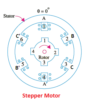
Both the rotor and stator have a definite number of teeth to suit the designed step angle. The step angle is defined as the angular displacement of the rotor in response to each pulse.
The rotor position depends upon the step angle and the number of pulses. The speed of rotation depends upon the rate of pulses (and not supply voltage) are precisely controlled; thus making the stepper motor an ideal drive for operations involving precise positioning. Unlike control and servo motors, no feedback control winding is required to close the loop and monitor the position and speed of the rotor.
The stepper motor working principle is explained in Figure. The rotor takes a position as per excitation of winding:
- In position (a) only winding A is energized.
- In position (b) both the windings, A and B are energized.
- In position (c), winding B is energized and so on.
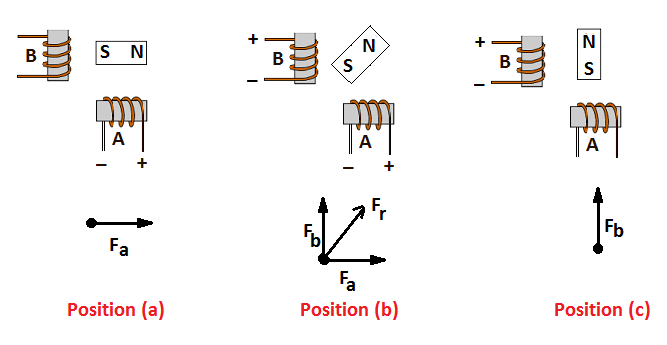
From the above illustration, you can understand easily that we can rotate the rotor in steps by supplying current to stator coils in a specific sequence. This is what we do in stepper motors.
A stepper motor system must accelerate and de-accelerate at a rate that allows the motor to overcome the system inertia. For this reason, rotors are constructed with less diameter and longer lengths. If a stepper motor is dynamically overloaded, it will slip phase. These motors are best suited for applications where loads are well within the capacity of the motor.
Holding torque is the maximum load torque that can be overcome by the motor without causing the rotor to slip from its stable equilibrium position.
The operation of a stepper motor is accurate and precise over a wide range of speed. Accuracy tolerance is the maximum deviation from nominal values of each rotor displacement in response to input pulse under no-load condition. The accuracy tolerance is usually in the range of 3 to 5% and this error is non-cumulative.
Response Range of Stepper Motor
If the switching rate is progressively increased, a point is reached where any further increase in switching rate cannot accelerate the motor from standstill to synchronous speed. The motor is said to have reached “pull-in” rate. The motor can function as a stepper motor responding to start-stop commands only within this switching rate, also called its ‘response range.’
If the switching rate is further increased, the motor operates within slewing range where it does not respond to start and stop commands but develops enough torque to overcome the load torque. Further increase in switching rate results in motor pulling out of step.
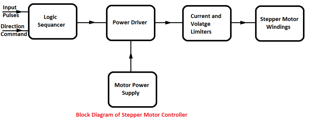
Stepper Motor Controller
The block diagram of a typical stepper motor controller is shown in Figure. The windings are energized in a definite sequence at the desired rate. Since the output signals of logic sequences are too weak to energize the motor windings, the same are used to drive thyristors which in turn supply power to the windings.
Resonance in Stepper Motor
The rotor oscillates due to inertial effect about each new position and this effect is more marked at slow speeds. If the step frequency corresponds to one of the backward peaks of these oscillations, the motor may occasionally jump back in phase instead of stepping forward. This effect is known as resonance in the stepper motor and can disturb the operation. The simplest solution is not to operate near the resonance zone. Other measures to overcome the problem would be:
- Operation in half step mode.
- Improved damping.
- Use of damping resistors between phases.
Applications of Stepper Motors
The most familiar application of stepper motors is in quartz analog watches. Because of the simplicity of logic controls, precision, and reliability, stepper motors are extensively used in computers peripherals, in CNC machine tools, remote controls, instrumentation, etc.
In computers, card readers, punched paper tape readers, teleprinters, digital X-ray plotters, dot matrix printers, the reading/writing heads of floppy and Winchester discs all use stepper motors as positioning drives. Two-phase motors are used for very light torque applications. Mostly higher power stepper motors are of the 3 or 4-phase types.
Thanks for reading about “working principle of stepper motor”.