An encoder is a sensor that converts rotational or linear displacement into digital signals.
As shown in Figure 1, a typical optical encoder consists of: (1) light source (LED), (2) code disk, (3) stationary mask, (4) light detector (photodetector), and (5) signal conditioning circuit.

The disk sits between the light source and the photodetector. As the disk rotates, the pattern on it blocks or lets the light pass through the disk. The stationary mask ensures proper alignment of the light with the photodetectors. As a result, the detector signal turns on or off. There are two main types of encoders:
- incremental and
- absolute.
They follow the same operating principle but use different patterns on the disk.
Incremental Encoder Working Principle
A rotary incremental encoder produces a series of pulses as the disk rotates. Figure 2 shows a typical disk with one track. The black-and-white pattern is evenly distributed along the circumference of the disk. These disks can be mounted on various hubs. The disk is then inserted in a detector unit to complete the core of the encoder assembly.

Figure 3 shows the digital pulses generated by a single detector as the disk pattern passes by it.

A circuit in the motion controller can count the number of pulses as the shaft rotates. If the number of counts per revolution is known, then the motion controller can convert the accumulated pulse count into angular distance traveled by the shaft.
However, we cannot tell whether the shaft is rotating clockwise or counterclockwise. In either direction, the controller would get pulses that look the same. This problem can be solved if a second detector is added as shown in Figure 3.
The detectors can be placed 90∘ E apart. One electrical cycle of the digital pulses consists of one high and one low pulse. One electrical cycle is equal to 360∘ E. Hence, when the two detectors are placed 90∘ E apart and side by side, each will point to a quarter of the electrical cycle.
This arrangement creates the so-called quadrature signal pattern out of two channels CH A and CH B. When the disk moves, the alternating pattern seen by the detectors generates two square waveforms that are shifted in phase by 90∘ E.
One approach to determine the direction of rotation is to monitor which channel detects the first edge transition or change in its signal. Figure 4 shows an arbitrary starting position where both detectors happen to be pointing at the black area; hence, both signals are low.

If the disk moves right, the CH A signal will change to high first. If the disk moves left, the CH B signal will transition to high first. Hence, by checking which channel senses the first signal change, we can tell if the disk is moving right or left.
If each black area is considered to be a radial line on the disk, going along the circumference from the leading edge of one black line to the leading edge of the next black line is a period of the waveform observed in one of the channels.

As shown in Figure 5, there are four edge transitions in one period. Therefore, if the motion controller circuit can count each edge transition, then the number of lines on an encoder disk can effectively be multiplied by 4.
For example, if an encoder has 2000 lines, then 8000 counts will correspond to one revolution. In other words, this encoder will have a resolution of 360∘ M/8000 = 0.045∘/ct. Lines per revolution (LPR) or pulses per revolution (PPR) are terms used in describing how many lines an incremental encoder disk has.
In Figure 2, the main track with the black-and-white pattern is along the circumference of the disk. But on this disk, there is also a second track inside the main track. This track is all white except for a single mark at the top. This mark is called the index pulse which is often CH C on a typical encoder. This pulse is generated once per revolution. It is often used by motion controllers during home position search for an axis.
Incremental encoders are also available as linear encoders (linear scales). The operating principle is the same as the rotary encoders. However, the code disk is replaced by a linear strip with the code printed on it. They are used to measure displacement along a linear axis.
SinCos Encoders
SinCos (sine-cosine) encoders are incremental encoders with analog outputs. Unlike the discrete on/off outputs of the incremental encoders, the SinCos encoders provide two sinusoidal outputs shifted by 90∘ in phase. Hence, they are also known as sinusoidal encoders.
The signals are generated using sinusoidal detectors. Industry standard for SinCos encoders is 1V peak-to-peak sine/cosine voltages [1, 4]. Due to the low voltage analog output signals, these encoders are sensitive to noise. As a result, complimentary channels are used for each signal.
In addition, to avoid having to use negative power supply, typically 2.5 V DC offset is added to the signals as shown in Figure 6. Each of the two analog channels provides a number of sine wave cycles per revolution as shown in Figure 6.

For example, a SinCos encoder may provide (1024 = 210) sine wave cycles out of each channel in one revolution of its shaft. This corresponds to the lines per revolution in the incremental encoders.
A unique feature of the SinCos encoders is the ability to interpolate their output signals. This requires a special circuitry with analog-to-digital (A/D) converters in the motion controller. At a specific point in a single sine wave cycle (360∘ electrical), analog signals VA and VB are read from the channels.
If channel A is the cosine channel and channel B is the sine channel, then arc tangent of the ratio of these two voltages will give the interpolated incremental electrical angle traveled within that sine wave cycle. Hence,

where n is the resolution of the A/D converter used in digitizing the analog channel signals. The arc tangent function tan−1 must be handled carefully by checking the sign of the sine and cosine signals to identify the correct quadrant for the angle.
The circuitry also counts the number of sine wave cycles, ncycles. Since each sine wave cycle can be digitized into 2n bits by the A/D converter, the shaft position can be determined in counts as
CTSpos = ncycles ⋅ 2n + CTSinterp
Complimentary Channels
Electrical noise, such as due to the transients generated by the switching power electronics in the drive, can interfere with the encoder signals leading to wrong position counts. Shielded, twisted-pair cables need to be used and good wiring practices must be followed.
An effective way to reduce the impact of noise is to use complimentary signals and balanced differential line drivers (EIA standard RS422). In this approach, each encoder channel has its complimentary channel, which is inverted as shown in Figure 7.

Both quadrature and SinCos encoders come with complementary (differential) channels. They are often labeled as CH A+, CH A−, CH B+, CH B−, and CH C+, CH C− (or Index+, Index−). The inverted signals allow bigger voltage swings (such as 0–10 V instead of the usual 0–5 V outputs) and, therefore, are more immune to noise. Line drivers are differential amplifiers. They increase the output current of each channel to “drive” the signal along the cable between the encoder and the controller. As shown in Figure 8, the differential line driver gets the signal from the encoder and inverts it to create the complimentary signal.

These signals are then sent to the controller through the shielded, twisted-pair cable. Since the two wires are in the same environment, any electrical noise will affect both of them in a similar way. On the controller side, a differential receiver will invert the CH A− signal again and combine it with the CH A+ signal. The common-mode noise induced on the signals is rejected by the differential amplifier and the original CH A+ signal of the encoder is extracted. There are line drivers on each of the encoder channels.
Absolute Encoder
An incremental encoder can measure a relative distance by counting the pulses. If the counting is referenced to a specific point, such as a home position or the index pulse on the encoder, then position can also be measured relative to that point. However, if there is a loss of power, the counts will be lost.
Similarly, when the machine is first powered up, it is not possible to know the position of an axis with an incremental encoder before homing is completed. An absolute encoder uses a disk that generates a unique digital code for each position of the disk.
Therefore, the absolute position of the shaft can be determined at any time, even during power up. If an axis uses an absolute encoder, there is no need to move it to a known reference point (home position) in the power up sequence. The resolution of an absolute encoder is determined by the number of bits in its output. Figure 9 shows 3-bit encoder disks. In this case, the encoder has three detectors, one on each track. The smallest position change that can be detected is 360∘∕23 = 45∘. Absolute encoders with 12-bits are common, which can detect 360∘∕212 = 0.088∘. The absolute encoder disk can have a binary code as shown in Figure 9(a).
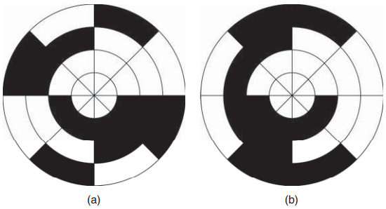
code disc.
Each sector (45∘ slice in this case) corresponds to the three-digit code in the Table given below. However, due to small misalignment between the detectors during the manufacturing of the encoder, the bits of the binary code may not transition all at the same time as the disk rotates from one sector to the next. As a result, the encoder may appear to be jumping from the current track to another track which is not adjacent to the current one.

To remedy this problem, Gray code is commonly used. It is much less likely to produce a wrong reading since only 1-bit at a time changes as the disk rotates from one sector to the next. Even if there were manufacturing imperfections, due to the single-bit change from sector to sector, the error in the position reading would be only as much as one sector (e.g., 0.088∘ in a 12-bit encoder).
A single-turn absolute encoder can provide a unique code for each angular position within one revolution of the shaft. However, if the shaft rotates more than one revolution, then the codes will be repeated.
A multiturn absolute encoder can count the number of revolutions and store them. It contains a gear train with high-precision gears. Each gear has its own code disk to count the turns. Multiturn encoders with 4-code disks are available. The code disks on the turn counters typically use the 4-bit Gray code (= 16 steps).

Every time the main disk (first disk) completes a revolution, the second disk advances by one count. When the second disk finishes a complete revolution, the third disk advances by one count. Similarly, when the third disk finishes a complete revolution, the fourth disk advances by one count.
Thanks for reading about “incremental encoder working principle”.