When a current flows through a thin flat conductor placed in a magnetic field, the magnetic field exerts a transverse force (i.e., Lorentz force) on the moving charge carriers and pushes them to one side of the conductor. The charge then builds up and forms a measurable voltage between the two sides of the conductor. This voltage is called Hall voltage and this phenomenon is called Hall Effect.
Hall Sensor Working Principle
Hall sensors operate based on the Hall effect. A thin sheet of metal or semiconductor material (Hall plate) with a current passing through it is placed in a magnetic field, and then a voltage is generated perpendicular to the field and the direction of current flow. Since the Hall voltage is small, Hall sensors require amplification and signal conditioning.
A distinguished feature of a Hall sensor is that it can be entirely integrated on a single silicon chip containing the Hall sensor, amplifier and signal conditioning circuits inside. This allows the low-cost and high-volume production of Hall sensors. Thus, Hall sensors are usually surface-mount types and can be mounted on a PCB (printed circuit board).
Characteristics of Hall Sensors
The key characteristics of Hall sensors can be described as follows.
Transfer Function: A Hall sensor’s transfer function describes its input and output relationship, characterized by sensitivity, null offset, and span.
Sensitivity is defined as the change in output resulting from a given change in input. Null offset is the output from a sensor with no magnetic field excitation. Span defines the output range of a sensor. Span is the difference in output voltages when the input is varied from a negative extreme to a positive extreme.

Figure 1 illustrates the characteristics of a typical analog Hall sensor under three different supplied voltages—5, 8, and 10 V, respectively. Its transfer function can be expressed by the relationship between a magnetic field input (in Gauss, G) and a voltage output (in V) as
Vout = (6.25 × 10⁻⁴ Vs )B + 0.5 Vs
Note this equation is valid only if the flux density B in the core has not reached saturation level, that is, −640 (Gauss) < B < +640 (Gauss). The factor of B, 6.25 × 10⁻⁴ Vs, in the equation expresses the sensitivity for the sensor, and it is the slope of each characteristic curve (a straight line in this case) in Figure 1. The second term in Equation 5.6, 0.5 Vs, is the null offset, which is the output voltage at 0 G under a given supply voltage.
Sensitivity (or Gain): A Hall sensor’s sensitivity can be characterized in two ways
- Volts per unit magnetic field, per unit of bias current: V/(B × I), in V ⋅ T−1 ⋅ A−1
- Volts per unit magnetic field, per unit of bias voltage: V/(B × V), in V ⋅ T−1 ⋅ V−1
Sensitivity of a Hall sensor varies slightly with temperature. Many sensor manufacturers provide sensitivity versus temperature curves in their datasheets to indicate their products’ stability with temperature variation. Signal conditioning electronics may be incorporated into Hall sensors to compensate temperature effects.
Ohmic Offset: An ohmic offset is a small voltage present in a sensor’s output, even in the absence of a magnetic field. This offset appears in almost all Hall sensors. It limits the ability of a sensor in discriminating a small steady-state magnetic field.
Many factors can cause ohmic offsets, including alignment error in the sensor’s contacts, inhomogeneities or stresses in the sensing material. An ohmic offset can be expressed by the output voltage for given bias conditions or in terms of magnetic field units. For instance, sensor A has a 500 μV offset, while sensor B has a 200 μV offset.
Nonlinearity: Similar to many other sensors, Hall sensors are not perfectly linear over their operating ranges. They typically exhibit a nonlinearity between 0.5% and 1.5% over their operating ranges.
Input and Output Resistance and Their Temperature Coefficient: Input resistance of Hall sensors affects the design of the bias circuitry, while the output resistance affects the design of the amplifier circuitry used to detect the Hall voltage (see Figure 2).

The temperature coefficients of the input and output resistances of Hall sensors should be equal or very close to each other since their difference will affect the measurement accuracy.
Noise: Hall sensors also present electrical noise at their outputs, mainly Johnson noise and sometimes flicker noise (1/f noise).
Johnson noise occurs in all conductive materials due to the random and thermally induced motion of electrons through a conductor (also called thermal noise). 1/f or flicker noise is more significant when detecting DC or near DC low-frequency signals. It depends on the sensing material used and the fabrication processes.
Johnson noise limits how small a sensor signal can be recovered from its output. It can be minimized by choosing a low impedance sensor.
Keep the following things in mind when using Hall sensors:
- Using a voltage drive rather than a current drive can reduce the temperature effect on the Hall output voltage VH.
- Constant voltage bias has a larger signal-to-offset ratio than constant current bias.
- Dual or quad Hall elements provide a higher magnetic sensitivity and smaller offsets.
- Hall voltage VH is very small, so use high amplification for Hall sensors. The DC offset of an amplifier often limits the usefulness of the VH
- The use of twisted or shielded cables can attenuate influence of static and dynamic electric and magnetic fields.
- A Hall sensor’s bandwidth is limited by magnetic core losses and eddy current-induced temperature rise.
- Hall sensors should be orientated correctly.
Types of Hall Sensors
Hall sensors have many configurations: vertical, cylindrical, multiaxis, dual, or quad. Traditional Hall elements are built in the plane of the chip surface as shown in Figure 3.

In this situation, the Hall element is only sensitive to the magnetic field that is perpendicular to the chip surface. The contacts for the input current and Hall output voltage are on the different faces.

Vertical Configurations: A vertical Hall sensor (VHS), as shown in Figure 4, responds to the magnetic field parallel to the plane of the chip and allows all electrical contacts to be placed on the top surface of the chip so that it can be easily manufactured using microelectronic fabrication processes. The Hall voltage is measured between the contacts. This configuration greatly improves both sensitivity (about 10 times greater than that of conventional Hall devices) and VH output (about 20 times greater than that of standard Hall sensors).

Figure 5 shows three configurations of VHSs for different applications.
(a) is a basic one-dimensional (1D) VHS;
(b) consists of two VHSs laid in a cross shape for measuring magnetic fields in both x and y (2D) directions; and
(c) is a three-branch VHS for three-phase brushless micromotor control.
Cylindrical Configurations: If the magnetic field being measured has a circular geometry, as around a current carrying wire, a cylindrical configuration provides the best solution.
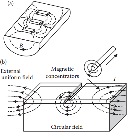
Figure 6(a) shows a cylindrical Hall sensor (CHS) made by a conformal deformation of a vertical Hall device. It can measure a circular magnetic field around a current-carrying wire or around an air gap of two FM flux concentrators as shown in Figure 6(b).
The sensitivity of this cylindrical Hall device can be as high as 2000 V ⋅ A−1 ⋅ T−1 due to the integrated magnetic flux concentrators. Its resolution is 70 nT.

Figure 7 shows a magnetic angular position sensor and its operating principle. It contains six high-sensitivity CHSs mounted on a ceramic substrate. A cylindrical Hall device equipped with FM field concentrators is very sensitive. However, its sensitivity decreases when the field value reaches the saturation value of the concentrator material (e.g., 20 mT). The drawback of a CHS is its nonlinearity.
Multiaxis Configurations: A multiaxis (2D or 3D) Hall sensor is used to measure more than one component of a magnetic field simultaneously. Such a sensor can be achieved by merging two or three mutually orthogonal vertical Hall devices.
Hall sensors that contain two or four Hall elements in one package are called dual or quad Hall sensors, respectively. This arrangement makes Hall sensors more stable and predictable than using several individual Hall sensors.
It also minimizes the effects of mechanical or thermal stress on the output. In addition, its rail-to-rail operation over a full voltage range provides a more usable signal with higher accuracy.
Applications of Hall Sensors
Hall sensors are widely used in automobile, security, brushless DC motors, damper control, various instrumentation, or any applications that involve electric current or magnetic field measurements. High-quality Hall sensors can be constructed inexpensively with the standard IC processes used in the microelectronics industry, and integrate ancillary signalprocessing circuitry on the same silicon die. Following are some application examples of Hall-effect sensors.
Hall Current Sensor: Hall sensors measure current via the intensity of the magnetic field generated by current flow. A larger current produces a stronger magnetic field. A Hall sensor’s output voltage is therefore directly proportional to the current. Hall sensors can measure both AC and DC currents, and pulsed waveforms (e.g., PWM—pulse width modulation signals).

Figure 8 illustrates a Hall current sensor. A C-core of soft magnetic material is placed around a conductor to concentrate the field. The Hall sensor, placed in the small air gap, delivers a voltage that is proportional to the current in the conductor.
Hall current sensors are usually surface-mount types that can be mounted on a PCB to measure the current in the traces. Hall current sensors have advantages of maintaining galvanic isolation between the sensor and the measuring circuits, and measuring the current without interrupting the circuit.

Flow Rate Meter: Hall sensors can also be used to measure flow rate (see Figure 9). Two Hall sensors measure the rotational velocity of the metal rotor that relates to the flow rate of a liquid transmitted through a pipe. The rotor is modified to have four recessed areas that have magnetic properties on their surfaces. The two Hall sensors pickup the magnetic field changes due to the rotor’s rotation, and the signals are converted into the flow rate.
Motor Control: Hall sensors are broadly used in brushless DC motor control due to their following features:
- Fast response time (<5 μs)
- Capability to detect high speed (theoretically can detect maximum of 16 × 105 rpm)
- Over-current sensing and stepper motor stall detection
- Support for closed-loop regulation
Hall sensors can provide two-phase, three-phase, and quad-phase motor control, implemented by using either two or more discrete Hall sensors or a single multiaxis Hall sensor.
For two-phase brushless motor control, one can use two individual Hall sensors that are oriented 90o apart (or a single two-axis Hall sensor) on the end of a brushless DC motor and a magnet attached on the end of the motor shaft. The advantage of using a 2-axis Hall sensor, instead of two discrete Hall sensors, is to eliminate the physical mounting tolerances of the discrete Hall sensors.
Thanks for reading about “hall sensor working principle”.