Synchro has a single winding rotor that rotates inside a stator of three windings, much like an electric motor as shown in Figure 1. The primary winding wound around the rotor is excited by an alternating current, which induces currents to flow in three Y-connected secondary windings (oriented 120° apart).
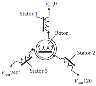
The relative magnitudes of secondary currents are measured to determine the angle of the rotor relative to the stator, or the currents can be used to directly drive a receiver synchro that will rotate in unison with the synchro transmitter. In the latter case, the whole system is often called a selsyn (a portmanteau of self and synchronizing).
A synchro provides accurate angular and rotational information. Since synchros have three stator coils in a 120° orientation, they are more difficult than resolvers to manufacture and are therefore more costly. Today, synchros find decreasing use, except in certain military and avionic retrofit applications.
Synchro Working Principle
A synchro is essentially a variable coupling transformer that uses the principle of electromagnetic induction. The magnitude of the magnetic coupling between the primary and secondary windings varies according to the position of the rotating element.
Traditionally, the simplest synchro system contains two parts: synchro transmitter and synchro receiver. The synchro transmitter consists of a singlephase, salient-pole (dumbbell-shaped) rotor and three-phase Y-connected stator.
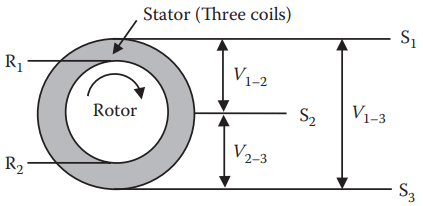
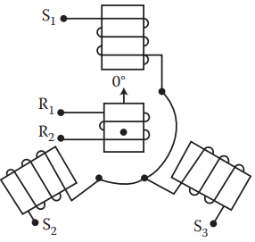
As shown in Figure 2, the primary coil (usually driven at 400 Hz) is the rotor and has two terminals (R1 and R2). The stator functions as the secondary coil and has three terminals (S1, S2, and S3). There are three stator coils in a 120° orientation and they are electrically Y-connected.
When a synchro emitter is driven by an AC current, the stator has three output voltages V1–2, V2–3, and V1–3. The transmitter equations show that nowhere over the entire 360° rotation of the rotor has the same set of voltages produced. Therefore, each set of voltage output (V1–2, V2–3, and V1–3) corresponds to a unique rotor position.
A receiver can take the three outputs V1–2, V2–3, and V1–3 from the emitter and transfer these three voltages into an angular position. Sometimes a receiver has its own rotor that rotates when receiving the three outputs from the emitter (V1–2, V2–3, V1–3).
The term “synchro” is an abbreviation of the word “synchronous,” which came from the fact that the receiver’s rotor rotates synchronously with the emitter’s rotor. Today, most synchros only contain a rotor (or emitter), and they rely on other means to determine the rotor’s position based on three voltage outputs.
Working Mechanism of Synchro Transmitter
The working mechanism of a synchro transmitter (see Figure 3) under a 115 V, 60 Hz AC excitation voltage applied to its rotor is as under:
When a 115 V, 60 Hz AC excitation voltage is applied to the rotor, the current in the rotor coil produces an AC magnetic field in the rotor winding and the core. The magnetic flux and force cut through the turns of the three stator windings and, by transformer action, induce voltage into the stator coils. The voltage induced in any stator coil depends upon the angular position of that coil’s axis with respect to the rotor axis. When the maximum effective coil voltage is known, the effective voltage induced into a stator coil at any angular displacement can be determined.
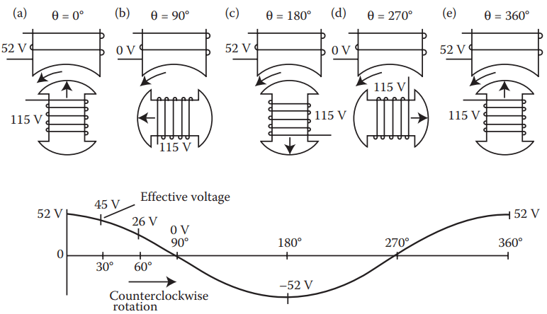
Figure 4 shows a cross section of a synchro transmitter and the effective voltage induced in one stator coil as the rotor rotates to different positions. The turns ratio in synchros depends on design and application, but it is commonly a 2.2:1 step down between the rotor and a single stator coil.
Thus, for 115 V applied voltage to the rotor, the highest value of effective voltage induced in any one stator coil is 52.27 V, which occurs whenever there is maximum magnetic coupling between the rotor and the stator coil (views a, c, and e).
The effective voltage induced in the secondary winding is approximately equal to the product of the effective voltage on the primary, the secondary-to-primary turns ratio, and the magnetic coupling between primary and secondary.
Since the primary voltage and the turns ratio are constant, the secondary voltage varies with the angle between the rotor and the stator. When stator voltages are measured, reference is always made to terminal-to-terminal voltages (voltage induced between two stator terminals) instead of to a single coil’s voltage.
This is because the voltage induced in one stator winding cannot be measured because the common connection between the stator coils is not physically accessible. In summary, the synchro transmitter converts the angular position of its rotor into electrical stator signals (voltages).
Resolver Working Principle
Resolver has a single-winding rotor that rotates inside a stator of two windings and provides accurate angular and rotational information.
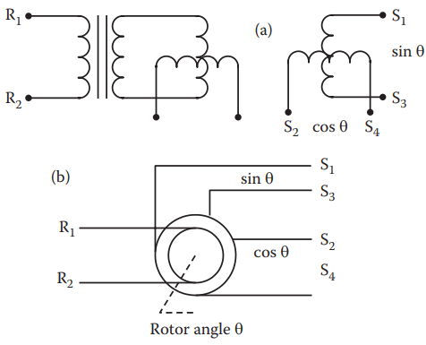
A resolver is basically a rotating transformer with one primary winding and two secondary windings that are phased 90° (see Figure 5a). As the rotor turns, the amplitude of the secondary voltage changes, modulating the input carrier. This establishes two separate outputs having a sine/cosine relationship.
As shown in Figure 5b, it accepts an AC excitation through terminals R1 and R2 at the rotor and produces a pair of two-wire outputs: sin θ (between terminals S1 and S3) and cos θ (between terminals S2 and S4), where θ is the angular position of the rotor. The position of the rotor can then be calculated by
θ = arctan(sin θ/cos θ)
Synchros are more difficult than resolvers to manufacture and are therefore more costly. Today, synchros find decreasing use, except in certain military and avionic retrofit applications.
Features of Synchros and Resolvers
Synchros resemble motors—consisting of a rotor, stator, and a shaft. Usually, slip rings and brushes connect the rotor to external power. A synchro can have single or three-phase configuration.
Single-phase units have five wires: two for an exciter winding (positive and negative ends) and three for the output. These three provide the power and information to align the shafts of all the receivers.
Synchro transmitters and receivers must be powered by the same branch circuit. Threephase synchro can handle more power and operate more smoothly. The excitation is often a 240 V 3-phase main power. Synchros designed for terrestrial use tend to be driven at 50 or 60 Hz, while those for marine or aeronautical use tend to operate at 400 Hz.
Multispeed synchros have stators with many poles, so that their output voltages go through several cycles for one physical revolution.
Differential synchros have three-lead rotors and stators, and can be transmitters or receivers. A differential transmitter is connected between a synchro transmitter and a receiver, and its shaft’s position adds to (or subtracts from) the angle defined by the transmitter. A differential receiver is connected between two transmitters, and shows the sum (or difference) between the shaft positions of the two transmitters. Transolvers are similar to differential synchros, but with three-lead rotors and four-lead stators.
The main parameters of resolvers are as follows:
Input voltage: 1 – 26 V. Larger voltage can cause the saturation of a resolver’s magnetic structure, resulting in increased error and null voltage.
Frequency: 400–5000 Hz frequency. Lower frequency can result in the saturation of a resolver’s magnetic structure, increase errors, and change some other parameters. Higher frequencies may result in increased magnetic flux leakage as well as changes in capacitance coupling.
Voltage sensitivity or voltage gradient: defined by the output voltage per one degree (1°) rotor rotating angle.
Transformation ratio (TR): defined as the ratio of output voltage to input voltage when the output is at maximum coupling, that is
TR = Max{Vout}/Vin
TR is approximately proportional to the ratio of effective turns, secondary N2 to primary N1:
TR = (KN2)/N1
Where K is a constant.
A higher TR is easy to achieve in one-speed resolvers. However, it is more difficult to achieve in multispeed resolvers because of increased flux leakage and increased N2 using very fine magnetic wire that complicates the manufacturing process.
Phase shift: the difference between the time phase of the primary and secondary voltage when the output is at maximum coupling.
Null voltage: the residual voltage at the point of minimum magnetic coupling between the primary and secondary windings. It is measured when the “in-phase” secondary voltage is zero.
Number of speeds: the number of amplitude-modulated sinusoidal cycles in one revolution of the resolver. Multiple-speed resolvers are achieved by increasing the number of magnetic poles in the rotor and stator equally. Increasing the number of speeds can increase the accuracy, but it is limited to the size of the resolver.
A single-speed resolver is essentially a single-turn absolute device. By increasing the speeds of a resolver, the absolute information is lost. If space permits, mounting a single-speed resolver on top of a multiple-speed resolver will provide higher accuracy and absolute information.
Applications of Synchros and Resolvers
Synchros and resolvers offer extremely high accuracy and fast measurement, and are used in industrial metrology, radar antennae, and telescopes.
Synchros are found in just about every weapon system, communication system, underwater detection system, and navigation systems. They are reliable, adaptable, and compact.
Resolvers lend themselves to maximum applications because of their simple and standard components similarity to electric motors (windings, laminations, and bearings). The most popular use of resolvers is in permanent magnet brushless AC servo motors, military, and aerospace applications.
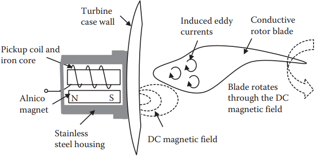
Figure 6 is a DC-biased eddy-current speed sensor developed by Hood Technology Corporation, Hood River, Oregon, USA. It can be mounted on the outside of the engine case (no holes and no interruption in the gas path) to monitor the turbine engine’s blade-tip speed, even in the presence of contaminants and at temperatures up to 1000°F.
With a permanent magnet the sensor generates a static magnetic field that penetrates nonferromagnetic engine case walls. As a conductive rotor blade passes through the sensor’s magnetic field, the eddy current is induced in the blade tip, creating the secondary magnetic field that interacts with the sensor’s magnetic field. The resulting perturbation in the field is detected by the sensor’s pickup coil as an induced voltage.
Based on Faraday’s law of electromagnetic induction, if N is fixed, the induced voltage is a function of only the time-rate change of the magnetic flux. Since some component, such as an engine case, is fixed to the sensor face, the penetrated flux in the material will not change as time changes. Therefore, it will not contribute to the induced voltage. Only the moving blades on the other side of the wall change the magnetic flux, resulting in an induced voltage.
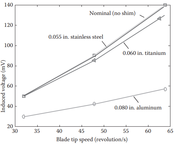
Figure 7 shows the sensor’s output, the induced voltage, versus the speed of a two-blade titanium rotor with three different test shims between the sensor and the rotor. Here, the nominal gap between the rotor and the sensor is 0.160 in. The thickness and material of each nonferromagnetic shim are 0.080 in. aluminum
0.060 in. titanium
0.055 in. stainless steel
As can be seen in Figure 7, the presence of stainless steel was the same as the nominal case (no shim); titanium reduced the output voltage signal by ~10%, and aluminum reduced it by ~50%. This result proves that increased electrical conductivity in the case of material resistance changes in magnetic flux and thus attenuates the sensor signal. However, the signal amplitude increases with increased electrical conductivity and magnetic permeability of the blades.