Piezoresistive Pressure Sensors
Piezoresistive sensors (also known as strain-gage sensors) are the most common type of pressure sensor in use today. Piezoresistive effect refers to a change in the electric resistance of a material when stresses or strains are applied.
Piezoresistive materials can be used to realize strain gages that, when incorporated into diaphragms, are well suited for sensing the induced strains as the diaphragm is deflected by an applied pressure.
The sensitivity of a strain gage is expressed by its gage factor, which is defined as the fractional change in resistance, ∆R/R, per unit strain:
Gage factor = (∆R/R)/ε
Where strain ε is defined as ∆L/L, or the extension per unit length. It is essential to distinguish between two different cases in which the strain is parallel to the direction of the current flow (along which the resistance change is to be monitored) and the strain is perpendicular to the direction of the current flow.
The gage factors associated with these two cases are known as the longitudinal gage factor and the transverse gage factor, respectively. The two gage factors are generally different in magnitude and often opposite in sign. Typical longitudinal gage factors are ∼2 for many useful metals, 10 – 35 for polycrystalline silicon (polysilicon), and 50 – 150 for single-crystalline silicon. Because of its large piezoresistive effect, silicon has become the most commonly used material for strain gages.
There are several ways to incorporate strain gages into pressure-sensing diaphragms. For example, strain gages can be directly bonded onto a metal diaphragm. However, hysteresis and creep of the bonding agent are potential issues. Alternatively, the strain-gage material can be deposited as a thin film on the diaphragm. The adhesion results from strong molecular forces that will not creep, and no additional bonding agent is required.
Today, the majority of piezoresistive pressure sensors are realized by integrating the strain gages into the silicon diaphragm using integrated circuit fabrication technology.
Silicon Micromachined Pressure Sensors
Silicon micromachined pressure sensors refer to a class of pressure sensors that employ integrated circuit batch processing techniques to realize a thinned-out diaphragm sensing element on a silicon chip.
Strain gages made of silicon diffused resistors are typically integrated on the diaphragm to convert the pressure-induced diaphragm deflection into an electric resistance change.
Over the past 20 years, silicon micromachined pressure sensors have gradually replaced their mechanical counterparts and have captured over 80% of the pressure sensor market. There are several unique advantages that silicon offers.
Silicon is an ideal mechanical material that does not display any hysteresis or yield and is elastic up to the fracture limit. It is stronger than steel in yield strength and comparable in Young’s modulus.
The piezoresistive effect in single-crystalline silicon is almost two orders of magnitude larger than that of metal strain gages. Silicon has been widely used in integrated circuit manufacturing for which reliable batch fabrication technology and high-precision dimension control techniques have been well developed.
A typical silicon wafer yields hundreds of identical pressure sensor chips at very low cost. Further, the necessary signal-conditioning circuitry can be integrated on the same sensor chip no more than a few millimeters in size. All these are key factors that contributed to the success of silicon micromachined pressure sensors.
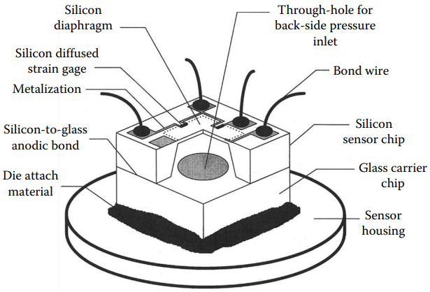
Figure 1 shows a typical construction of a silicon piezoresistive pressure sensor. An array of square or rectangular diaphragms is “micromachined” out of an (100) oriented single-crystalline silicon wafer by selectively removing material from the back. An anisotropic silicon etchant (e.g., potassium hydroxide) is typically employed; it etches fastest on surfaces and much slower on surfaces.
The result is a pit formed on the backside of the wafer bounded by surfaces and a thinned-out diaphragm section on the front at every sensor site. The diaphragm thickness is controlled by a timed etch or by using suitable etch-stop techniques.
To realize strain gages, a p-type dopant, typically boron, is diffused into the front of the n-type silicon diaphragm at stress-sensitive locations to form resistors that are electrically isolated from the diaphragm and from each other by reverse biased p–n junctions. The strain gages, the diaphragm, and the rest of the supporting sensor chip all belong to the same single-crystalline silicon.
The result is a superb mechanical structure that is free from creep, hysteresis, and thermal expansion coefficient mismatches. However, the sensor die must still be mounted to a sensor housing, which typically has mechanical properties different from that of silicon.
It is crucial to ensure a high degree of stress isolation between the sensor housing and the sensing diaphragm that may otherwise lead to long-term mechanical drifts and undesirable temperature behavior. A common practice is to bond a glass wafer or a second silicon wafer to the back of the sensor wafer to reinforce the overall composite sensor die. This way, the interface stresses generated by the die mount will also be sufficiently remote from the sensing diaphragm and will not seriously affect its stress characteristics.
For gage or differential pressure sensing, holes must be provided through the carrier wafer prior to bonding that are aligned to the etch pits of the sensor wafer leading to the back of the sensing diaphragms. No through holes are necessary for absolute pressure sensing. The wafer-to-wafer bonding is performed in a vacuum to achieve a sealed reference vacuum inside the etch pit.
Today’s silicon pressure sensors are available in a large variety of plastic, ceramic, metal can, and stainless steel packages.
Many are suited for printed circuit board mounting. Others have isolating diaphragms and transfer fluids for handling corrosive media. They can be readily designed for a wide range of industrial, medical, automotive, aerospace, and military applications.
Silicon Piezoresistive Pressure Sensor Limitations
Despite the relatively large piezoresistive effects in silicon strain gages, the full-scale resistance change is typically only 1% – 2% of the resistance of the strain gage (which yields an unamplified voltage output of 10 – 20 mV/V).
To achieve an overall accuracy of 0.1% of full scale, for example, the combined effects of mechanical and electric repeatability, hysteresis, linearity, and stability must be controlled or compensated to within a few parts per million (ppm) of the gage resistance. Furthermore, silicon strain gages are also very temperature sensitive and require careful compensations. There are two primary sources of temperature drifts:
- the temperature coefficient of resistance of the strain gages (from 0.06%/°C to 0.24%/°C) and
- the temperature coefficient of the gage factors (from −0.06%/°C to −0.24%/°C), which will cause a decrease in pressure sensitivity as the temperature rises.
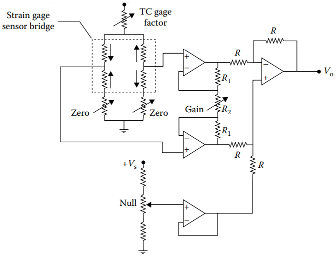
Figure 2 shows a circuit configuration that can be used to achieve offset (resulting from gage resistance mismatch) and temperature compensations as well as providing signal amplification to give a high-level output.
Four strain gages that are closely matched in both their resistances and temperature coefficients of resistance are employed to form the four active arms of a Wheatstone bridge. Their resistor geometry on the sensing diaphragm is aligned with the principal strain directions so that two strain gages will produce a resistance increase and the other two a resistance decrease on a given diaphragm deflection.
These two pairs of strain gages are configured in the Wheatstone bridge such that an applied pressure will produce a bridge resistance imbalance while the temperature coefficient of resistance will only cause a common-mode resistance change in all four gages, keeping the bridge balanced.
As for the temperature coefficient of the gage factor, because it is always negative, it is possible (e.g., with the voltage divider circuit in Figure 2) to utilize the positive temperature coefficient of the bridge resistance to increase the bridge supply voltage, compensating for the loss in pressure sensitivity as temperature rises.
Another major limitation in silicon pressure sensors is the nonlinearity in the pressure response that usually arises from the slight nonlinear behavior in the diaphragm mechanical and the silicon piezoresistive characteristics.
The nonlinearity in the pressure response can be compensated by using analog circuit components. However, for the most accurate silicon pressure sensors, digital compensation using a microprocessor with correction coefficients stored in memory is often employed to compensate for all the predictable temperature and nonlinear characteristics.
The best silicon pressure sensors today can achieve an accuracy of 0.08% of full scale and a long-term stability of 0.1% of full scale per year. Typical compensated temperature range is from −40 °C to 85 °C, with the errors of compensation on span and offset both around 1% of full scale.
Commercial products are currently available for full-scale pressure ranges from 10 kPa to 70 MPa (1.5 – 10,000 psi).