Thermocouple Junction Styles
Junction designs vary widely for specialized application. Most junctions are very localized. Some, to average surface temperature along a line, have widely extended a junction between foil thermoelements. Measuring and reference junctions are conspicuous. However, the many incidental junctions are inconspicuous and may not be recognized yet, uncontrolled; their temperatures can significantly degrade accuracy.
Contact Junctions
The area of contact between thermoelements has no influence on the Seebeck emf if thermometry is performed under proper nulled-current conditions. An electrical point contact is as effective as contact over a broad area.
A pair of pointed probe tips contacting a conducting subject closely spaced can serve as the measuring junctions to measure local temperature. The characteristic emf difference between a pair of well-spaced thermocouples with contact measuring junctions heated at two different controlled temperatures can be used to identify metals. Temporary measuring junctions can be formed merely by holding or taping together crossed thermoelements.
Thermoelements accidentally shorted by contact apart from the measuring junction monitor temperature where shorted, not at the intended measuring junction. In calibration, ends of thermoelements often are electrically connected to extensions by immersing bare tips into a bridging isothermal pool of mercury in an ice bath.
Intrinsic Thermocouples
If the subject of thermometry is an electrically conductive material, tips of the two thermoelements can be fused directly to the test subject as by spot welding. These form junctions of an “intrinsic” thermocouple.
Closely spaced fine wires or thin foils spot-welded to the subject allow the fastest possible electro-thermal response and reduce the influence of the thermocouple on the temperature being measured.
For fastest response, the two thermoelements should be fused to the subject nearly in contact side-by-side or end-to-end (but not one over the other). As the fused spots are very close together, they tend to be nearly isothermal even in transient thermometry so any bridging conductive subject material has negligible effect on the Seebeck emf.
However, if the points of fusion are widely separated, the non-isothermal bridging conductor of indefinite thermoelectric property can contribute spurious emf to the measurement while the two weld spots are at different transient temperatures.
For transient thermometry, the thermoelements at the intrinsic junctions should be short and as fine as feasible to reduce thermal loading. A strain-relieved transition from the fine filaments to more substantial corresponding-type extension wires should be made.
The effect of circuit capacitance or inductance on electrical response is significant only in transient thermometry. As the intrinsic junction is electrically common to the subject, circuit grounding and isolation must be appropriate.
Twisted Junctions
A temporary junction contact can be formed merely by twisting together ends of dissimilar wire thermoelements. Twisted junctions may also be soldered or tip-welded for strength.
Such robust elongated connections do not affect the Seebeck emf as the sensing junctions are the dual interfaces where the adjacent thermoelements first contact the twisted section.
The mass of the extended twisted section only slows thermal response and thereby can affect the temperatures of the junctions and the subject. Such junctions are not used for transient thermometry.
Fused Junctions
The familiar “bead-junction” style of thermocouple is formed by fusion of paired thermoelements. Specialized thermocouple welders perform the melt in a localized inert atmosphere to reduce local oxidation of the thermoelements. The spheroidal bead is neither the “junction” nor an emf source. Its purity is irrelevant.
The bead is an indeterminate thermoelement alloyed from the joined thermoelements. It is the interfaces between the bead and thermoelements that are junctions. They function as one if the bead is isothermal.
Compact junctions are formed by spot welding of crossed thermoelements. The free ends can be trimmed to leave a small robust junction. A very compact junction can also be formed as a smooth “butt-weld” for thermoelement wires as small as 0.003 in. diameter fused end-to-end.
Enclosed Junctions
The metal sheath of a mineral-insulated (MIMS) style thermocouple usually encloses two or more thermoelements. Thermoelements can be of different thermocouple types. Thermoelements may be paired with separate junctions or several legs may share a common junction as a “tip-branched” thermocouple.
Junctions usually are enclosed within the sheath and are either isolated from or made electrically common with the closed sheath tip. Isolated “junctions” are fused beads insulated within the enclosed end of the sheath.
A form with junctions electrically common to the sheath tip inappropriately is termed a “grounded junction” even though it may not be electrically common with the important circuit “electrical ground” point (i.e., “grounded” junctions might be electrically “isolated” from electrical power reference ground).
Alternatively, bead-style junctions, bare or insulated, can extend outside the sheath for faster response. The sheath end must be sealed immediately and remain sealed. A short span of the MIMS material tip that includes enclosed junctions can be drawn to reduced diameter.
Such thermoelements are reduced proportionately in diameter. The reduced tip diameter speeds transient response and localizes temperature measurement.
Specialized Thermocouple Assemblies
Measuring Junction Assemblies: The simple Seebeck phenomenon invites more diverse specialty thermometry designs than any other thermal sensing technology. Seebeck would be astonished! Process, industrial, and scientific applications for thermocouples now are specialized to diverse applications.
Manufacturer’s catalogs present dozens of variations. These fabricated assemblies may conceal the functional measuring junction and adjacent thermoelements and circuit components within housings that are designed for convenient handling and for protection.
Thermoelements of these specialty forms might be subjected to degrading mechanical treatment in fabrication. The irregular geometries and size, and the fact that sensitivity is distributed rather than localized to the measuring junction, complicate calibration and homogeneity verification.
Most specialized thermocouple assemblies are of the dual-reference-junction circuit style of Figure 1, except that they contain many more inconspicuous incidental junctions and thermoelements.
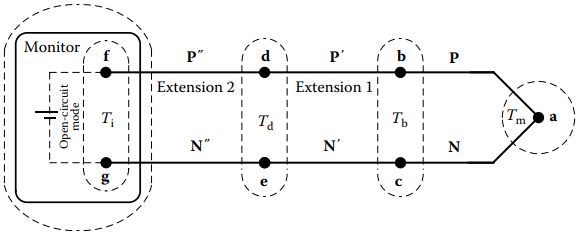
For ease of connection, each packaged measuring junction assembly is fitted with a thermocouple plug connector that mates through a connector jack to extension cables or instruments.
The concealed measuring junction, incidental junctions, thermoelements, and extensions are subject internally to all the problems illustrated by the Functional Model for dual-reference junction circuits.
The distributed nature of the Seebeck emf requires an authentic understanding of thermoelectric circuits to recognize sources of significant thermoelectric error concealed within assemblies.
Reference Junction Assemblies: Most specialized thermocouple assemblies are for use as measuring junctions. As a convenience, a few thermocouple assemblies are specialized to physically apply the 0 °C temperature references as in Figure 2
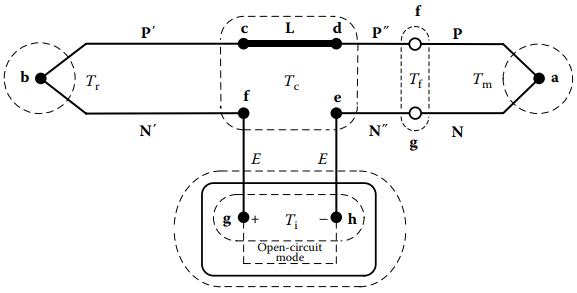
Such reference junction assemblies form most of the thermoelectric circuit as they combine the reference junction with extension leads and connectors. The separate measuring thermocouple simply plugs into the assembly.
Though convenient, that reference system is not best suited for accurate calibration. Resembling a regular color-coded connector, an optional battery-powered Reference Temperature Compensator can bridge the measuring thermocouple and its passive extension with regular thermocouple plug and jack connectors.
Inserted near the measuring thermocouple assembly, the compensator electronically applies reference voltage to place the reference junctions effectively at the conventional 0 °C reference temperature. This component, used only with passive-style extensions, is usually joined directly to the measuring thermocouple or its “active” extensions.
If this local reference is used, the remote monitor must not redundantly apply additional compensation. The connector-like reference is small so it allows the reference compensation to be individually oven-calibrated over the temperature range near ambient temperature.
Wells: Process thermometry may require the measuring junction to be isolated from a chemically damaging or mechanically abrasive environment, sealed from pressure or vacuum, or to isolate a sanitary process from the thermocouple.
Thermometry, as of incinerators, thermal reactors, and coal gasifiers, is a severe challenge because vibration and the chemical environment are particularly destructive of refractory thermocouples required for the high temperatures.
Thermocouple-specialized metal, ceramic, or plastic wells extending sealed into a process allow replacement of the sensor without interruption. These rugged thick-walled metal or ceramic wells separate the junction from direct contact with the process so they are used for thermometry of steady or slowly varying temperatures.
Special wells can flow protective gases along the thermoelements adjacent to the junction. The wells usually are used with MIMS thermocouples that must be seated and thermally coupled in good thermal contact with the well.
These massive protections with lengthy immersion depths also beneficially tend to place the measuring junction in a nearly isothermal region where locally degraded segments near the junction contribute less spurious emf.
Related Posts
- Thermocouple Working Principle
- Absolute Seebeck Effect
- Basic Thermocouple Circuits
- Extensions of Thermocouple
- Functional Model of Thermoelectric Circuits
- T/X Sketch of Dual-Reference Junction Circuit
- Applications of Functional Model
- Characteristics of Thermocouples
- Thermocouple Hardware
- Thermocouple Junction Styles
- Active Tests of Thermocouple
- Calibration of Thermocouples
- Thermocouple Thermometry Practice
- Distinctive Thermocouple Noise Problems