A counter is a logic circuit that can count a sequence of numbers or states when activated by a clock input. The output of a counter indicates the binary number stored in the counter at any given time. The number of counts or states through which a counter progresses before returning to its original state (recycling) is called the modulus of the counter. A flip-flop can act as a simple counter when connected as shown in Figure 1.

Assuming that initially the flip-flop is reset, the first clock pulse causes it to set (Q = 1). The second clock pulse causes it to reset (Q = 0). Because the flip-flop has set and reset, two clock pulses have occurred.
Figure 2 shows the output waveform of the flip-flop. Notice that the Q output is high (1) after every odd clock pulse and low (0) after every even clock pulse. Therefore, when the output is high, an odd number of clock pulses has occurred.

When the output is low, either no clock pulses or an even number of clock pulses has occurred. In this case, it is not known which has occurred. A single flip-flop produces a limited counting sequence, 0 or 1.
To increase the counting capacity, additional flip-flops are needed. The maximum number of binary states in which a counter can exist depends on the number of flip-flops in the counter. This can be expressed as:
N = 2n
Where: N = maximum number of counter states
n = number of flip-flops in counter
Binary counters fall into two categories based on how the clock pulses are used to sequence the counter. The two categories are asynchronous and synchronous.
Operation of Asynchronous Counter
Asynchronous means not occurring at the same time. With respect to counter operations, asynchronous means that the flip-flops do not change states at the same time. This is because the clock pulse is not connected to the clock input of each stage. Figure 3 shows a two-stage counter connected for asynchronous operation. Each flip-flop in a counter is referred to as a stage.

Notice that the output of the first stage is coupled to the clock input of the second stage. The second stage only changes state when triggered by the transition of the output of the first stage. Because of the delay through the flip-flop, the second flip-flop does not change state at the same time the clock pulse is applied. Therefore, the two flip-flops are never simultaneously triggered, which results in asynchronous operation.
Asynchronous counters are commonly referred to as ripple counters. The input clock pulse is first felt by the first flip-flop. The effect is not felt by the second flip-flop immediately because of the delay through the first flip-flop. In a multiple-stage counter, the delay is felt through each flip-flop, so that the effect of the input clock pulse “ripples” through the counter.
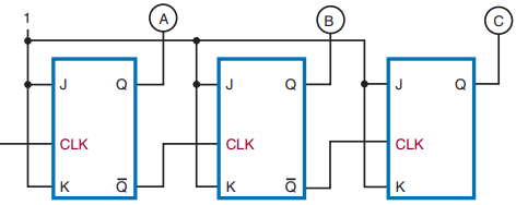


Figure 4 shows a three-stage binary counter and timing chart for each of the stages. A truth table is also shown to show the counting sequence.
Operation of Synchronous Counter
Synchronous means occurring at the same time. A synchronous counter is a counter in which each stage is clocked at the same time. This is accomplished by connecting the clock input to each stage of the counter (Figure 5).


A synchronous counter is also called a parallel counter because the clock input is connected in parallel to each flip-flop. A synchronous counter operates as follows.
Initially the counter is reset with both flip-flops in the 0 state. When the first clock pulse is applied, the first flip-flop toggles and the output goes high. The second flip-flop does not toggle because of the delay from the input to the actual changing of the output state. Therefore, there is no change in the second flip-flop output state.
When the second clock pulse is applied, the first flip-flop toggles and the output goes low. Because there is a high from the output of the first stage, the second stage toggles and its output goes high. After four clock pulses, the counter recycles to its original state.
Figure 6 shows a timing chart for this sequence of events with a two-stage synchronous counter.
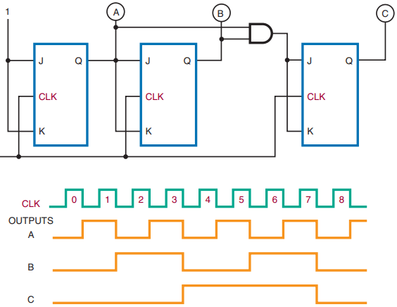

Figure 7 shows a three-stage binary counter and timing chart. Figure 8 shows a four-stage synchronous counter and logic symbol.


One application of a counter is frequency division. A single flip-flop produces an output pulse for every two input pulses. Therefore, it is essentially a divide-by-two device with an output one-half the frequency of the input.
A two-stage binary counter is a divide-by-four device with an output equal to one-fourth the input clock frequency. A four-stage binary counter is a divide-by-sixteen device with the output equal to one-sixteenth the input clock frequency (Figure 9).


A binary counter with n stages divides the clock frequency by a factor of 2n. A three-stage counter divides the frequency by eight (23), a four-stage counter by sixteen (24), a five-stage counter by thirty-two (25), and so on. Notice that the modulus of the counter is the same as the division factor.

Decade counters have a modulus of ten, or ten states in their counting sequence. A common decade counter is the BCD (8421) counter, which produces a binary-coded-decimal sequence (Figure 10).
The AND and OR gates detect the occurrence of the ninth state and cause the counter to recycle on the next clock pulse. The symbol for a decade counter is shown in Figure 11.


An up-down counter can count in either direction through a certain sequence. It is also referred to as a bidirectional counter. The counter can be reversed at any point in the counting sequence. Its symbol is shown in Figure 12.
An up-down counter can consist of any number of stages. Figure 13 shows the logic diagram for a BCD up-down counter. The inputs to the JK flip-flops are enabled by the up-down input qualifying the up or down set of the AND gates.

Counters can be stopped after any sequence of counting by using a logic gate or combination of logic gates. The output of the gate is fed back to the input of the first flip-flop in a ripple counter. If a 0 is fed back to the JK input of the first flip-flop (Figure 14) it prevents the first flip-flop from toggling, thereby stopping the count.
