Boolean Equation for Logic Gate Circuits
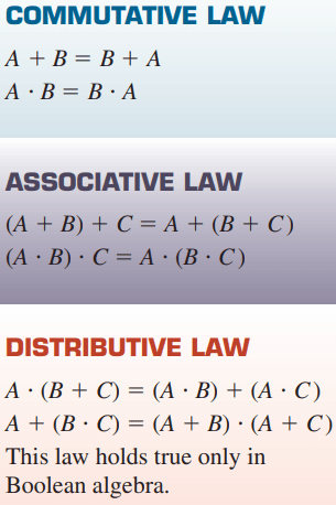
An understanding of the technique of writing simplified Boolean equations for complex logical statements is a useful tool when creating PLC control programs. Some laws of Boolean algebra are different from those of ordinary algebra. These three basic laws illustrate the close comparison between Boolean algebra and ordinary algebra, as well as one major difference between the two:
Developing Logic Gate Circuits from Boolean Expressions
As logic gate circuits become more complex, the need to express these circuits in Boolean form becomes greater.
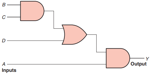
Figure 1 shows a logic gate circuit developed from the Boolean expression Y = A(BC + D). The procedure is as follows:
Boolean expression: Y = A(BC + D)
Gates required: (by inspection)
- 1 – AND gate with input B and C
- 1 – OR gate with inputs B, C, and D
- 1 – AND gate with inputs A and the output from the OR gate
Producing Boolean Equation for Logic Gate Circuits
A simple logic gate is quite straightforward in its operation. However, by grouping these gates into combinations, it becomes more difficult to determine which combinations of inputs will produce an output.
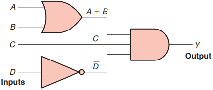
The Boolean equation for the logic circuit of Figure 2 is determined as follows:
- The output of the OR gate is A + B
- The output of the inverter is D̄
- Based on the input combination applied to the AND gate the Boolean equation for the circuit is Y = C D̄ (A + B)
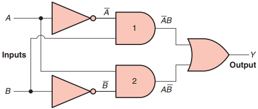
The Boolean equation for logic gate circuit of Figure 3 is determined as follows:
- The output of AND gate 1 is ĀB
- The output of AND gate 2 is AB̄
- Based on the combination of inputs applied to the OR gate the Boolean equation for the circuit is Y = ĀB + AB̄
Hardwired Logic versus Programmed Logic
The term hardwired logic refers to logic control functions that are determined by the way devices are electrically interconnected. Hardwired logic can be implemented using relays and relay ladder schematics. Relay ladder schematics are universally used and understood in industry.
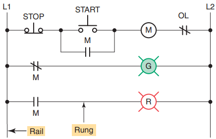
Figure 4 shows a typical relay ladder schematic of a motor stop/start control station with pilot lights. The control scheme is drawn between two vertical supply lines. All the components are placed between these two lines, called rails or legs, connecting the two power lines with what look like rungs of a ladder—thus the name, relay ladder schematic.
Hardwired logic is fixed; it is changeable only by altering the way devices are electrically interconnected. In contrast, programmable control is based on the basic logic functions, which are programmable and easily changed.
These functions (AND, OR, NOT) are used either singly or in combinations to form instructions that will determine if a device is to be switched on or off. The form in which these instructions are implemented to convey commands to the PLC is called the language. The most common PLC language is ladder logic.
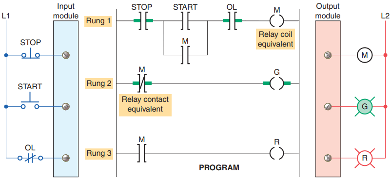
Figure 5 shows a typical ladder logic program for the motor start/ stop circuit. The instructions used are the relay equivalent of normally open (NO) and normally closed (NC) contacts and coils.
PLC contact symbolism is a simple way of expressing the control logic in terms of symbols. These symbols are basically the same as those used for representing hardwired relay control circuits. A rung is the contact symbolism required to control an output.
Some PLCs allow a rung to have multiple outputs while others allow only one output per rung. A complete ladder logic program then consists of several rungs, each of which controls an output.
In programmed logic all mechanical switch contacts are represented by a software contact symbol and all electromagnetic coils are represented by a software coil symbol. Because the PLC uses ladder logic diagrams, the conversion from any existing relay logic to programmed logic is simplified.
Each rung is a combination of input conditions (symbols) connected from left to right, with the symbol that represents the output at the far right.
The symbols that represent the inputs are connected in series, parallel, or some combination of the two to obtain the desired logic.
The following group of examples illustrates the relationship between the relay ladder schematic, the ladder logic program, and the equivalent logic gate circuit.
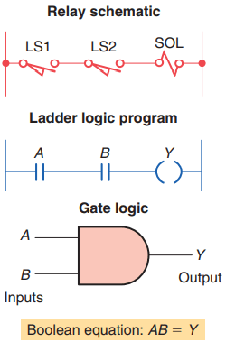
Example 1. Two limit switches connected in series and used to control a solenoid valve.
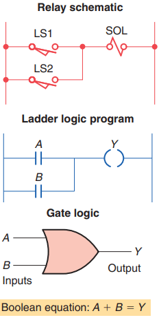
Example 2. Two limit switches connected in parallel and used to control a solenoid valve.
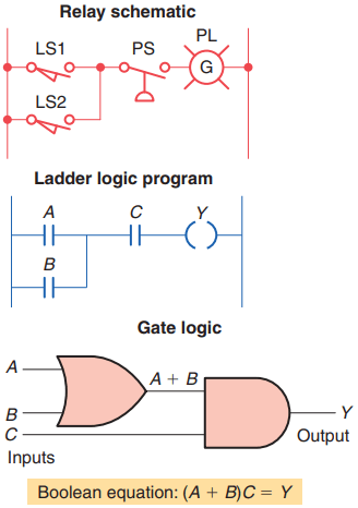
Example 3. Two limit switches connected in parallel with each other and in series with a pressure switch.
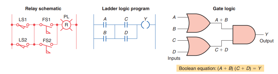
Example 4. Two limit switches connected in parallel with each other and in series with two sets of flow switches (that are connected in parallel with each other), and used to control a pilot light.
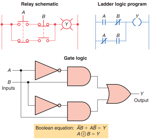
Example 5. Exclusive-OR circuit. The output lamp of this circuit is ON only when pushbutton A or B is pressed, but not both. This circuit has been programmed using only the normally open A and B pushbutton contacts as the inputs to the program.
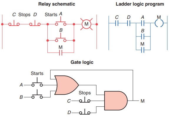
Example 6. A motor control circuit with two start/stop buttons. When either start button is depressed, the motor runs. By use of a seal-in contact, it continues to run when the start button is released. Either stop button stops the motor when it is depressed.