Central Processing Unit of PLC
The central processing unit (CPU) is built into single-unit fixed PLCs while modular rack types typically use a plug-in module. CPU, controller, and processor are all terms used by different manufacturers to denote the same module that performs basically the same functions. Processors vary in processing speed and memory options. A processor module can be divided into two sections:
- the CPU section and
- the memory section ( Figure 1).
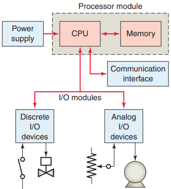
The CPU section executes the program and makes the decisions needed by the PLC to operate and communicate with other modules. The memory section electronically stores the PLC program along with other retrievable digital information.
The PLC power supply provides the necessary power (typically 5 VDC) to the processor and I/O modules plugged into the backplane of the rack. Power supplies are available for most voltage sources encountered. The power supply converts 115 VAC or 230 VAC into the usable DC voltage required by the CPU, memory, and I/O electronic circuitry.
PLC power supplies are normally designed to withstand momentary losses of power without affecting the operation of the PLC. Holdup time, which is the length of time a PLC can tolerate a power loss, typically ranges from 10 milliseconds to 3 seconds.
The CPU contains the similar type of microprocessor found in a personal computer. The difference is that the program used with the microprocessor is designed to facilitate industrial control rather than provide general-purpose computing. The CPU executes the operating system, manages memory, monitors inputs, evaluates the user logic (ladder program), and turns on the appropriate outputs.
Central Processing Unit of PLC
The CPU of a PLC system may contain more than one processor. One advantage of using multiprocessing is that the overall operating speed is improved. Each processor has its own memory and programs, which operate simultaneously and independently. In such configurations the scan of each processor is parallel and independent thus reducing the total response time.
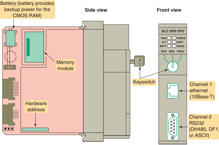
Fault-tolerant PLC systems support dual processors for critical processes. These systems allow the user to configure the system with redundant (two) processors, which allows transfer of control to the second processor in the event of a processor fault. Associated with the processor unit will be a number of status LED indicators to provide system diagnostic information to the operator ( Figure 2 ). Also, a key-switch may be provided that allows you to select one of the following three modes of operation: RUN, PROG, and REM.
RUN Position
- Places the processor in the Run mode
- Executes the ladder program and energizes output devices
- Prevents you from performing online program editing in this position
- Prevents you from using a programmer/operator interface device to change the processor mode
PROG Position
- Places the processor in the Program mode
- Prevents the processor from scanning or executing the ladder program, and the controller outputs are de-energized
- Allows you to perform program entry and editing
- Prevents you from using a programmer/operator interface device to change the processor mode
REM Position
- Places the processor in the Remote mode: either the REMote Run, REMote Program, or REMote Test mode
- Allows you to change the processor mode from a programmer/operator interface device
- Allows you to perform online program editing
The processor module also contains circuitry to communicate with the programming device. Somewhere on the module you will find a connector that allows the PLC to be connected to an external programming device. The decision-making capabilities of PLC processors go far beyond simple logic processing. The processor performs other functions such as timing, counting, latching, comparing, motion control and complex math functions.
PLC processors have changed constantly due to advancements in computer technology and greater demand from applications. Today, processors are faster and have additional instructions added as new models are introduced. Because PLCs are microprocessor based, they can be made to perform tasks that a computer can do. In addition to their control functions, PLCs can be networked to do supervisory control and data acquisition (SCADA).
Many electronic components found in processors and other types of PLC modules are sensitive to electrostatic voltages that can degrade their performance or damage them. The following static control procedures should be followed when handling and working with static-sensitive devices and modules:
- Ground yourself by touching a conductive surface before handling static-sensitive components.
- Wear a wrist strap that provides a path to bleed off any charge that may build up during work.
- Be careful not to touch the backplane connector or connector pins of the PLC system (always handle the circuit cards by the edge if possible).
- Be careful not to touch other circuit components in a module when you configure or replace its internal components.
- When not in use, store modules in its static-shield bag.
- If available, use a static-safe work station.
Memory Design of PLC
Memory is the element that stores information, programs, and data in a PLC. The user memory of a PLC includes space for the user program as well as addressable memory locations for storage of data. Data are stored in memory locations by a process called writing. Data are retrieved from memory by what is referred to as reading .
The complexity of the program determines the amount of memory required. Memory elements store individual pieces of information called bits (for binary digits ). The amount of memory capacity is specified in increments of 1000 or in “K” increments, where 1 K is 1024 bytes of memory storage (a byte is 8 bits). The program is stored in the memory as 1s and 0s, which are typically assembled in the form of 16-bit words.
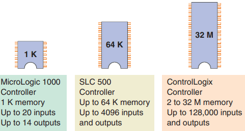
Memory sizes are commonly expressed in thousands of words that can be stored in the system; thus 2 K is a memory of 2000 words, and 64 K is a memory of 64,000 words. The memory size varies from as small as 1 K for small systems to 32 MB for very large systems ( Figure 3 ). Memory capacity is an important prerequisite for determining whether a particular processor will handle the requirements of the specific application.
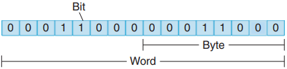
Memory location refers to an address in the CPU’s memory where a binary word can be stored. A word usually consists of 16 bits. Each binary piece of data is a bit and eight bits make up one byte ( Figure 4 ). Memory utilization refers to the number of memory locations required to store each type of instruction. A rule of thumb for memory locations is one location per coil or contact. One K of memory would then allow a program containing 1000 coils and contacts to be stored in memory.
The memory of a PLC may be broken into sections that have specific functions. Sections of memory used to store the status of inputs and outputs are called input status files or tables and output status files or tables ( Figure 5 ). These terms simply refer to a location where the status of an input or output device is stored. Each bit is either a 1 or 0, depending on whether the input is open or closed. A closed contact would have a binary 1 stored in its respective location in the input table, whereas an open contact would have a 0 stored.
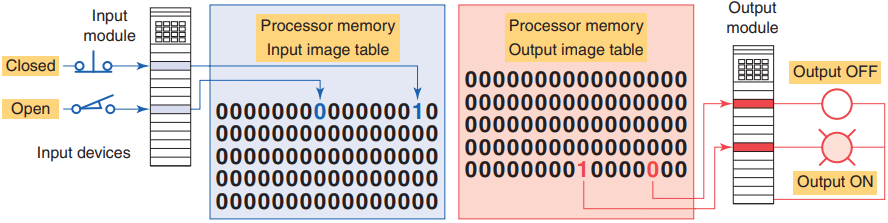
A lamp that is ON would have a 1 stored in its respective location in the output table, whereas a lamp that is OFF would have a 0 stored. Input and output image tables are constantly being revised by the CPU. Each time a memory location is examined, the table changes if the contact or coil has changed state.
PLCs execute memory-checking routines to be sure that the PLC memory has not been corrupted. This memory checking is undertaken for safety reasons. It helps ensure that the PLC will not execute if memory is corrupted.
Memory Types
Memory can be placed into two general categories: volatile and nonvolatile.
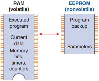
Volatile memory will lose its stored information if all operating power is lost or removed. Volatile memory is easily altered and is quite suitable for most applications when supported by battery backup. Nonvolatile memory has the ability to retain stored information when power is removed accidentally or intentionally.
As the name implies, programmable logic controllers have programmable memory that allows users to develop and modify control programs. This memory is made nonvolatile so that if power is lost, the PLC holds its programming.
Read Only Memory (ROM) stores programs, and data cannot be changed after the memory chip has been manufactured. ROM is normally used to store the programs and data that define the capabilities of the PLC. ROM memory is nonvolatile, meaning that its contents will not be lost if power is lost.
ROM is used by the PLC for the operating system. The operating system is burned into ROM by the PLC manufacturer and controls the system software that the user uses to program the PLC.
Random Access Memory (RAM), sometimes referred to as read-write (R/W) memory, is designed so that information can be written into or read from the memory. RAM is used as a temporary storage area of data that may need to be quickly changed. RAM is volatile, meaning that the data stored in RAM will be lost if power is lost. A battery backup is required to avoid losing data in the event of a power loss.
Most PLCs use CMOSRAM technology for user memory. CMOS-RAM chips have very low current draw and can maintain memory with a lithium battery for an extended time, two to five years in many cases. Some processors have a capacitor that provides at least 30 minutes of battery backup when the battery is disconnected and power is OFF.
Erasable Programmable Read-Only Memory (EPROM) provides some level of security against unauthorized or unwanted changes in a program. EPROMs are designed so that data stored in them can be read, but not easily altered without special equipment. For example, UV EPROMs (ultraviolet erasable programmable read-only memory) can only be erased with an ultraviolet light. EPROM memory is used to back up, store, or transfer PLC programs.
Electrically erasable programmable read-only memory (EEPROM) is a nonvolatile memory that offers the same programming flexibility as does RAM. The EEPROM can be electrically overwritten with new data instead of being erased with ultraviolet light. Because the EEPROM is nonvolatile memory, it does not require battery backup. It provides permanent storage of the program and can be changed easily using standard programming devices. Typically, an EEPROM memory module is used to store, back up, or transfer PLC programs ( Figure 6 ).
Flash EEPROMs are similar to EEPROMs in that they can only be used for backup storage. The main difference comes in the flash memory: they are extremely fast at saving and retrieving files. In addition, they do not need to be physically removed from the processor for reprogramming; this can be done using the circuitry within the processor module in which they reside.
Flash memory is also sometimes built into the processor module, where it automatically backs up parts of RAM. If power fails while a PLC with flash memory is running, the PLC will resume running without having lost any working data after power is restored.
Programming Terminal Devices of PLC
A programming terminal device is needed to enter, modify, and troubleshoot the PLC program. PLC manufacturers use various types of programming devices. The simplest type is the hand-held type programmer shown in Figure 7. This proprietary programming device has a connecting cable so that it can be plugged into a PLC’s programming port. Certain controllers use a plug-in panel rather than a hand-held device.
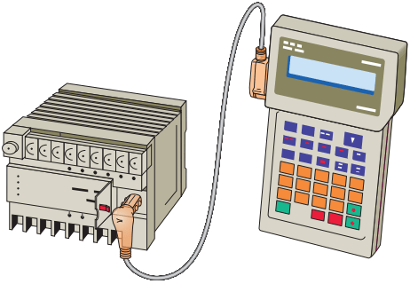
Hand-held programmers are compact, inexpensive, and easy to use. These units contain multifunction keys and a liquid-crystal display (LCD) or light-emitting diode (LED) window. There are usually keys for instruction entering and editing, and navigation keys for moving around the program. Hand-held programmers have limited display capabilities. Some units will display only the last instruction that has been programmed, whereas other units will display from two to four rungs of ladder logic. So-called intelligent hand-held programmers are designed to support a certain family of PLCs from a specific manufacturer.
The most popular method of PLC programming is to use a personal computer (PC) in conjunction with the manufacturer’s programming software. Typical capabilities of the programming software include online and offline program editing, online program monitoring, program documentation, diagnosing malfunctions in the PLC, and troubleshooting the controlled system. Hard-copy reports generated in the software can be printed on the computer’s printer.
Most software packages will not allow you to develop programs on another manufacturer’s PLC. In some cases, a single manufacturer will have multiple PLC families, each requiring its own software to program.
Recording and Retrieving Data
Printers are used to provide hard-copy printouts of the processor’s memory in ladder program format. Lengthy ladder programs cannot be shown completely on a screen. Typically, a screen shows a maximum of five rungs at a time. A printout can show programs of any length and analyze the complete program.
The PLC can have only one program in memory at a time. To change the program in the PLC, it is necessary either to enter a new program directly from the keyboard or to download one from the computer hard drive.
Some CPUs support the use of a memory cartridge that provides portable EEPROM storage for the user program. The cartridge can be used to copy a program from one PLC to another similar type PLC.
Human Machine Interfaces of PLC
A human machine interface (HMI) can be connected to communicate with a PLC and to replace pushbuttons, selector switches, pilot lights, thumbwheels, and other operator control panel devices. Luminescent touch-screen keypads provide an operator interface that operates like traditional hardwired control panels. Human machine interfaces give the ability to the operator and to management to view the operation in real time. Through personal computer–based setup software, you can configure display screens to:
- Replace hardwired pushbuttons and pilot lights with realistic-looking icons. The machine operator need only touch the display panel to activate the pushbuttons.
- Show operations in graphic format for easier viewing.
- Allow the operator to change timer and counter presets by touching the numeric keypad graphic on the touch screen.
- Show alarms, complete with time of occurrence and location.
- Display variables as they change over time.
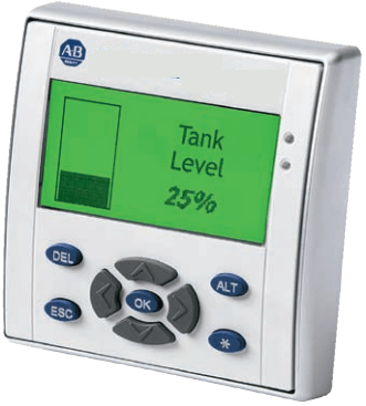
The Allen-Bradley Pico GFX-70 controller, shown in Figure 8, serves as a controller with HMI capabilities.
This device consists of three modular parts: an HMI, processor/power supply, and I/O modules. The display/keypad can be used as an operator interface or can be linked to control operations to provide realtime feedback.
It has the ability to show text, date and time, as well as custom messages and bitmap graphics, allowing operators to acknowledge fault messages, enter values, and initiate actions. Users can create both the control program and HMI functionality using a personal computer with PicoSoft Pro software installed or the controller’s on-board display buttons.
Thanks for reading about “central processing unit of PLC”.