Installation and Commissioning of PLC
A PLC system, if installed properly, should give years of trouble-free service. The design of PLCs includes a number of rugged features that allow them to be installed in almost any industrial environment. However, problems can occur if the system is not installed properly.
Programmable logic controllers (PLCs) require protection against temperature extremes, humidity, dust, shock, and vibration or corrosive environments. For these reasons, PLCs are generally mounted within a machine or in a separate enclosure.
An enclosure is the chief protection from atmospheric conditions. The National Electrical Manufacturers Association (NEMA) has defined enclosure types, based on the degree of protection an enclosure will provide.
For most solid-state control devices, a NEMA 12 enclosure is recommended. This type of enclosure is for general-purpose areas and is designed to be dust-tight. Typically, metal enclosures are used because metal enclosures provide shielding that helps minimize the effects of electromagnetic radiation that may be generated by surrounding equipment.
Every PLC installation will dissipate heat from its power supplies, local I/O racks, and processor. This heat accumulates in the enclosure and must be dissipated from it into the surrounding air. Excessive heat can cause erratic operation of the PLC or PLC failure.
For many applications, normal convection cooling will keep the controller components within the specified temperature operating range. Proper spacing of components that provides adequate room within the enclosure is usually sufficient for heat dissipation. The temperature inside the enclosure must not exceed the maximum operating temperature of the controller (typically 60°C maximum).
Additional cooling provisions, such as a fan or blower, may be required where high internal or ambient temperatures are encountered. PLCs are always mounted horizontally with the name of the manufacturer facing out and right-side up. Vertical mounting is not recommended due to thermal considerations.
A hardwired electro-mechanical master control relay (MCR) is normally included as part of the wiring for a PLC system. The master control relay provides a means of de-energizing the entire circuit that is not dependent on software. The internally programmed MCR of a PLC is not sufficient to meet safety requirements. The hardwired MCR is connected to interrupt power to the I/O rack in the event of an emergency, but still allow power to be maintained at the processor.

Figure 1 shows the typical wiring for an AC power distribution with a master control relay. The operation of the circuit can be summarized as follows:
- A power disconnect switch is provided so that, when required, the PLC can be serviced with the power off.
- The step-down transformer provides isolation from the main power distribution system and decreases the voltage to the 120 volts required for the controller power supplies and DC power supplies.
- The momentary start button is pressed to energize the master control relay.
- Pressing any one of the emergency-stop switches de-energizes the master control relay and thus de-energizes the I/O devices.
- Power to the processor of the PLC remains on so status LEDs can continue to provide up-to-date information.
- Emergency stop buttons use normally closed contacts wired in series for fail-safe operation. In the event a wire is broken or comes off a terminal, the MCR relay is de-energized and power is removed.
Electrical Noise
Electrical noise, also called electromagnetic interference, or EMI, is unwanted electrical signals that produce undesirable effects and otherwise disrupt the control system circuits.
EMI may be either radiated or conducted. Radiated noise originates from a source and travels through the air while conducted noise travels on an actual conductor, such as a power line. When the PLC is operated in a noise-polluted industrial environment, special consideration should be given to possible electrical interference.
To increase the operating noise margin, the controller should be located away from noise-generating devices such as large AC motors and high-frequency welders. Malfunctions resulting from noise are temporary occurrences of operating errors that can result in hazardous machine operation in certain applications.
Noise usually enters through input, output, and power supply lines. Noise may be coupled into these lines by an electrostatic field or through electromagnetic induction. The following reduce the effect of electrical interference:
- Manufacturer design features
- Proper mounting of the controller within an enclosure
- Proper equipment grounding
- Proper routing of wiring
- Proper suppression added to noise-generating devices
Noise suppression is normally needed for inductive loads such as relays, solenoids, and motor starters when operated by hard contact devices such as pushbuttons or selector switches. When inductive loads are switched off, high transient voltages are generated that if not suppressed can reach several thousand volts.
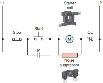
Figure 2 illustrates a typical noise suppression circuit that is used to suppress the high voltage spikes generated when a motor starter coil is de-energized. Lack of surge suppression on inductive loads may contribute to processor faults and sporadic operation. RAM can be corrupted (lost), and I/O modules can appear faulty or can reset themselves.
When inductive devices are energized or de-energized, they can cause an electrical pulse to be back-fed into the PLC system. The back-fed pulse, when entering the PLC system, can be mistaken by the PLC for a computer pulse. It takes only one false pulse to create a malfunction of the orderly flow of PLC operational sequences.
Proper routing of field power and signal wiring to the PLC enclosure as well as inside the enclosure helps to cut down on electrical noise. The following are some general guidelines for PLC wire routing:
- Use the shortest possible wire runs for I/O signals.
- When possible, conductors that are run from the PLC enclosure to another location should be in a metal conduit as the metal can serve as a shield against EMI.
- Never run signal wiring and power wiring in the same conduit.
- Segregate I/O wiring by signal type. Route AC and DC I/O signal wires in separate wireways.
- Low-level signal conductors such as thermocouples and serial communications should be run as shielded twisted pair and routed separately.
- A fiber optic system, which is totally immune to all kinds of electrical interference, can also be used for signal wiring.
An important part of a PLC installation is clearly identifying each wire to be connected and the terminal to which it is connected. A reliable labeling method, such as the heat-shrinkable wire identification sleeves, should be used to label each wire.
Wiring connectors for input/output modules usually includes spaces for labels used for identifying each I/O address and device connected. Proper wire and terminal identification will simplify the installation and aid in troubleshooting and maintenance.
Leaky Inputs and Outputs
Many electronic devices with transistor or triac outputs exhibit a small leakage current even when in the off state that may need to be considered when they are connected to PLC input modules. This so-called leakage is typically exhibited by two-wire proximity, photoelectric, and other such sensors. Often, the leaky input will only cause the module’s input indicator to flicker. However, a large enough leakage current can activate the input circuit, creating a false input signal.

A common solution to the problem of leaky input current is to connect a bleeder resistor across or in parallel with the input, as shown in Figure 3. The bleeder resistor acts as an additional lower resistance load, which allows the leakage current to flow through the lower resistance path. Typically a 10 kΩ to 20 kΩ resistor is used to solve the problem.
Leakage current may also occur with the solid-state switch used in many output modules. Problems similar to that encountered with input modules can be created when a high-impedance load device is used with these modules.

For example, a PLC output might supply a sound alert device as illustrated in Figure 4. In this case the leakage current could cause continuous false or intermittent operation. A resistor can be connected as shown to bleed off this current. An isolation relay could also be used to solve this type of problem.
Grounding
Proper grounding is an important safety measure in all electrical installations. The authoritative source on grounding requirements for a PLC installation is the National Electrical Code.
The NEC specifies the types of conductors, color codes, and connections necessary for safe grounding of electrical components. In addition, most manufacturers provide detailed information on the proper grounding methods to use in an enclosure.

Figure 5 illustrates a PLC grounding system. A properly installed grounding system will provide a low-impedance path to earth ground. The complete PLC installation, including enclosures, CPU and I/O chassis, and power supplies are all connected to a single low-impedance ground. These connections should exhibit low DC resistance and low high-frequency impedance.
A central ground bus bar is provided as a single point of reference inside the enclosure to which all chassis and power supply equipment grounding conductors are connected. The ground bus is then connected to the building’s earth ground.
In the event of a high value of ground current, the temperature of the conductor could cause the solder to melt, resulting in interruption of the ground connection. Therefore the grounding path must be permanent (no solder), continuous, and able to conduct safely the ground-fault current in the system with minimal impedance.
Paint or other non-conductive material should be scraped away from the area where a chassis makes contact with the enclosure. The minimum ground wire size should be No. 12 AWG stranded copper for PLC equipment grounds and No. 8 AWG stranded copper for enclosure backplane grounds. Ground connections should be made with a star washer between the grounding wire and lug and metal enclosure surface.
Ground loops can cause problems by adding or subtracting current or voltage from input signal devices. A ground loop circuit can develop when each device’s ground is tied to a different earth potential thereby allowing current to flow between the grounds, as illustrated in Figure 6 .

If a varying magnetic field passes through one of these ground loops, a voltage is produced and current flows in the loop. The receiving device is unable to differentiate between the wanted and unwanted signals and, thus, can’t accurately reflect actual process conditions. Certain connections require shielded cables to help reduce the effects of electrical noise coupling. Each shield should be grounded at one end only, as a shield grounded at both ends forms a ground loop.
Voltage Variations and Surges
The power supply section of the PLC system is built to sustain line fluctuations and still allow the system to function within its operating range. If voltage fluctuations exceed this range, then a system shutdown will occur.
In areas where excessive line voltage variation or extended brownouts are anticipated, installing a constant voltage (CV) transformer may be required to minimize nuisance shutdowns of the PLC. Isolation transformers are used in some PLC systems to isolate the PLC from electrical disturbances generated by other equipment connected to the distribution system.
Although the PLC is designed to operate in harsh environments, other equipment may generate considerable amounts of interference that may result in intermittent disturbances in normal operation. A normal practice is to place the PLC power supply and I/O devices on a separate transformer that may also serve as a step-down transformer to reduce the incoming voltage to the desired level.
When current in an inductive load is interrupted or turned off, a very high voltage spike is generated. This high voltage can be reduced or eliminated through suppression techniques which absorb the inductive induced voltage. Generally, output modules designed to drive inductive loads include suppression networks built in as part of the module circuit.
An additional external suppression device is recommended if an output module is used to control devices such as relays, solenoids, motor starters, or motors. The suppression device is wired in parallel (directly across) and as close as possible to the load device. The suppression components must be rated appropriately to suppress the switching transient characteristic of the particular inductive device.

Figure 7 illustrates how a diode is connected to suppress DC inductive loads. The operation of the circuit can be summarized as follows:
- The diode is connected in reverse-bias across the solenoid load.
- In normal operation, the electric current can’t flow through the diode, so it flows through the solenoid coil.
- When voltage to the solenoid is switched off a voltage opposite in polarity to the original applied voltage is generated by the collapsing magnetic field.
- The induced voltage creates a current flow through the diode bleeding off the high voltage spike.

Figure 8 illustrates how an RC (resistor/capacitor) snubber circuit is connected for suppressing AC load devices. The operation of the circuit can be summarized as follows:
- The voltage peak, which occurs at the instant the current path to the coil is opened, is safely short-circuited by the RC network.
- The resistor and capacitor connected in series slows the rate of rise of the transient voltage.
- The voltage across the capacitor cannot change instantaneously, so a decreasing transient current will flow through it for a small fraction of a second, allowing the voltage to increase more slowly when the circuit is opened.

The metal oxide varistor (MOV) surge suppressor, shown in Figure 9, is the most popular surge protection device. It functions in a manner similar to two zener diodes connected back-to-back. The operation of a MOV can be summarized as follows:
- The device acts as an open circuit until the voltage across it in either direction exceeds its rated value.
- Any greater voltage peak instantly makes the device act like a short circuit that bypasses this voltage away from the rest of the circuit.
Program Editing and Commissioning of PLC
After you have entered the rungs for your program, you may need to modify them. Editing is simply the ability to make changes to an existing program through a variety of editing functions. Using the editing function, instructions and rungs can be added or deleted; addresses, data, and bits can be changed. Again, the editing format varies with different manufacturers and PLC models.
Today, most PLC programming software is Microsoft Windows based, so if you are familiar with Windows and know how to point and click with a mouse, you should have no problem editing a program.
In general, both instructions and rungs are selected simply by clicking on them with the left mouse button. Double clicking with the left mouse button allows you to edit an instruction’s address, whereas right clicking displays a pop-up menu of related editing commands.
If you want to include additional explanation of a symbol or address, you can place an address description on your ladder rung directly above the symbol. To add a page or rung comment, right click on the rung number to which you wish to add the page or rung comment.
Preparing a control process for start-up, also called commissioning, involves a series of tests to ensure that the PLC, the ladder logic program, the I/O devices, and all associated wiring operate according to specifications.
Before commissioning any control system, you should have a good understanding of how the control system operates and how the various components interact. The following are general steps to be followed when commissioning a PLC system:
- Before applying power to the PLC or the input devices, disconnect or otherwise isolate any output device that could potentially cause damage or injury. Typically this precaution would pertain to outputs that cause movement such as starting a motor or operating a valve.
- Apply power to the PLC and input devices. Measure the voltage to verify that rated voltage is being applied.
- Examine the PLC’s status indicator lights. If power is properly applied, the power indicator should be on, and there should be no fault indication. If the PLC does not power up properly, it may be faulty. PLCs rarely fail, but if they do fail, it usually happens immediately upon powering up.
- Verify that you have communication with the PLC via the programming device that is running the PLC programming software.
- Place the PLC in a mode that prevents it from energizing its output circuits. Depending on the make of the PLC, this mode may be called disable, continuous test, or single-scan mode. This mode will allow you to monitor input devices, execute the program, and update the output image file while keeping the output circuits de-energized.
- Manually activate each input device, one at a time, to verify that the PLC’s input status lights turn on and off as expected. Monitor the associated condition instruction to verify that the input device corresponds to the correct program address and that the instruction turns true or false as expected.
- Manually test each output. One way you can do this is by applying power to the terminal where the output device is wired. This test will check the output field device and its associated wiring.
- After verifying all inputs, outputs, and program addresses, verify all preset values for counters, timers, and so on.
- Reconnect any output devices that may have been disconnected and place the PLC in the run mode. Test the operation of all emergency stop buttons and the total system operation.
Programming and Monitoring
When you program a PLC, several instruction entry modes are available, depending on the manufacturer and the model of the unit. A personal computer, with appropriate software, is generally used to program and monitor the program in the PLC.
Additionally, it makes possible offline programming, which involves writing and storing the program in the personal computer without its being connected to the PLC and later downloading it to the PLC.


Figure 10 illustrates how programs are downloaded and uploaded from and to the computer. With online programming the program can be modified, the modifications can be tested, and finally they can be accepted or rejected while the PLC is running.
However, offline programming is the safest manner in which to edit a program because additions, changes, and deletions do not affect the operation of the system until downloaded to the PLC.
Many manufacturers provide a continuous test mode that causes the processor to operate from the user program without energizing any outputs. This mode allows the control program to be executed and debugged while the outputs are disabled.
A check of each rung can be done by monitoring the corresponding output rung on the programming device. A single-scan test mode may also be available for debugging the control logic. This mode causes the processor to complete a single scan of the user program each time the single-scan key is pressed with no outputs being energized.
An online programming mode permits the user to change the program during machine operation. As the PLC controls its equipment or process, the user can add, change, or delete control instructions and data values as desired. Any modification made is executed immediately on entry of the instruction. Therefore, the user should assess in advance all possible sequences of machine operation that will result from the change.
Online programming should be done only by experienced personnel who understand fully the operation of the PLC they are dealing with and the machinery being controlled. If at all possible, changes should be made offline to provide a safe transition from existing programming to new programming.
Two useful monitoring tools provided with PLC programming packages are data monitor and cross reference. Data monitoring functions allow you to monitor and/or modify specified program variables. The cross reference function allows you to search each instance of a particular address.
The data monitor feature allows you to display data from any place in the data table. Depending on the PLC, the data monitor function can be used to do the following:
- View data within an instruction
- Store data or values for an instruction prior to use
- Set or reset values and/or bits during a debug operation for control purposes
- Change the radix or data format

Figure 11 shows the data file folder and window for the Allen-Bradley SLC 500 PLC and its associated RSLogix software. The data file folder allows the user to determine the status of I/O files as well as the status file (S2), binary file (B3), timer file (T4), counter file (C5), control file (R6), integer file (N7), and the floating-point file (F8).
Always be careful when manipulating data using the data monitor function. Changing data could affect the program and turn output devices on or off. When troubleshooting a PLC, it may be necessary to locate each instance of a particular address in the ladder program.
The cross reference function searches all program files to locate each instance of the selected address. A user can then trace the operation by finding all the places where a particular output coil or contact with the same address is used in the program.


Figure 12 shows a sample cross reference report for the Allen-Bradley SLC 500 PLC and its associated RSLogix software. Its contents can be summarized as follows:
- The report contains all the addresses used in the program.
- Addresses are displayed in the same order as the data table files.
- The address that the search was performed for (O:2/1) is highlighted.
- The description for each address is displayed.
- Listing includes the instruction type, program file, and rung number for each address.
- Each occurrence of the address is displayed, starting with program file 2 and rung 0.
The contact histogram function allows you to view the transition history (the on and off states) of a data table value. The status of the bit(s) (on or off) and the length of time the bit(s) remained on or off (in hours, minutes, seconds, and hundredths of a second) are displayed.
In a contact histogram file, the accumulated time indicates the total time that the histogram function was running. The delta time of the contact histogram indicates the elapsed time between the changes in states.
Contact histograms are extremely useful for detecting intermittent problems, either hardware- or logic-related. By tracking the status and time between status changes, you can detect different types of problems.
Preventive Maintenance of PLC
The biggest deterrent to PLC system faults is a proper preventive maintenance program. Although PLCs have been designed to minimize maintenance and provide trouble-free operation, there are several preventive measures that should be looked at regularly.
Many control systems operate processes that must be shut down for short periods for product changes. The following preventive maintenance tasks should be carried out during these short shutdown periods:
- Any filters that have been installed in enclosures should be cleaned or replaced to ensure that clear air circulation is present inside the enclosure.
- Dust or dirt accumulated on PLC circuit boards should be cleaned. If dust is allowed to build up on heat sinks and electronic circuitry, an obstruction of heat dissipation could occur and cause circuit malfunction. Furthermore, if conductive dust reaches the electronic boards, a short circuit could result and cause permanent damage to the circuit board. Ensuring that the enclosure door is kept closed will prevent the rapid buildup of these contaminants.
- Connections to the I/O modules should be checked for tightness to ensure that all plugs, sockets, terminal strips, and module connections are making connections and that the module is installed securely. Loose connections may result not only in improper function of the controller but also in damage to the components of the system.
- All field I/O devices should be inspected to ensure that they are adjusted properly. Circuit boards dealing with process control analogs should be calibrated every 6 months. Other devices, such as sensors, should be serviced on a monthly basis. Field devices in the environment, which have to translate mechanical signals into electrical, may gum up, get dirty, crack, or break—and then they will no longer trip at the correct setting.
- Care should be taken to ensure that heavy noise- or heat-generating equipment is not moved too close to the PLC.
- Check the condition of the battery that backs up the RAM memory in the CPU. Most CPUs have a status indicator that shows whether the battery’s voltage is sufficient to back up the memory stored in the PLC. If a battery module is to be replaced, it must be replaced with exactly the same type of battery module.
- Stock commonly needed spare parts. Input and output modules are the PLC components that fail most often.
- Keep a master copy of operating programs used.
To avoid injury to personnel and to prevent equipment damage, connections should always be checked with power removed from the system. In addition to disconnecting electrical power, all other sources of power (pneumatic and hydraulic) should be de-energized before someone works on a machine or process controlled by a PLC.
Most companies use lockout and tagout procedures, to make sure that equipment does not operate while maintenance and repairs are conducted. A personnel protection tag is placed on the power source for the equipment and the PLC, and it can be removed only by the person who originally placed the tag. In addition to the tag, a lock is also attached so that equipment cannot be energized.