Memory Map for PLC Processor
While the fundamental concepts of PLC programming are common to all manufacturers, differences in memory organization, I/O addressing, and instruction set mean that PLC programs are never perfectly interchangeable among different makers. Even within the same product line of a single manufacturer, different models may not be directly compatible. The memory map or structure for a PLC processor consists of several areas, some of these having specific roles.
Allen-Bradley PLCs have two different memory structures identified by the terms rack-based systems and tag-based systems. The memory organization for rack-based systems will be covered in this article and that for tag-based systems in a later article.
Memory organization takes into account the way a PLC divides the available memory into different sections. The memory space can be divided into two broad categories: program files and data files. Individual sections, their order, and the sections’ length will vary and may be fixed or variable, depending on the manufacturer and model.
Program files are the part of the processor memory that stores the user ladder logic program. The program accounts for most of the total memory of a given PLC system. It contains the ladder logic that controls the machine operation. This logic consists of instructions that are programmed in a ladder logic format. Most instructions require one word of memory.
The data files store the information needed to carry out the user program. This includes information such as the status of input and output devices, timer and counter values, data storage, and so on.
Contents of the data table can be divided into two categories: status data and numbers or codes. Status is ON/OFF type of information represented by 1s and 0s, stored in unique bit locations. Number or code information is represented by groups of bits that are stored in unique byte or word locations.
Memory Map for PLC Processor
The memory organizations of the rack-based AllenBradley PLC-5 and SLC 500 controllers are very similar. Figure 1 shows the program and data file organization for the SLC 500 controller. The contents of each file are as follows.
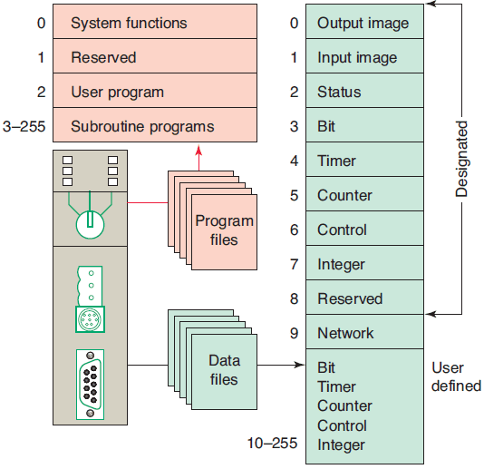
Program Files
Program files are the areas of processor memory where ladder logic programming is stored. They may include:
- System functions (file 0): This file is always included and contains various system-related information and user-programmed information such as processor type, I/O configuration, processor file name, and password.
- Reserved (file 1): This file is reserved by the processor and is not accessible to the user.
- Main ladder program (file 2): This file is always included and contains user-programmed instructions that define how the controller is to operate.
- Subroutine ladder program (files 3 – 255): These files are user-created and are activated according to subroutine instructions residing in the main ladder program file.
Data Files
The data file portion of the processor’s memory stores input and output status, processor status, the status of various bits, and numerical data. All this information is accessed via the ladder logic program. These files are organized by the type of data they contain and may include:
- Output (file 0): This file stores the state of the output terminals for the controller.
- Input (file 1): This file stores the status of the input terminals for the controller.
- Status (file 2): This file stores controller operation information and is useful for troubleshooting controller and program operation.
- Bit (file 3): This file is used for internal relay logic storage.
- Timer (file 4): This file stores the timer accumulated and preset values and status bits.
- Counter (file 5): This file stores the counter accumulated and preset values and status bits.
- Control (file 6): This file stores the length, pointer position, and status bit for specific instructions such as shift registers and sequencers.
- Integer (file 7): This file is used to store numerical values or bit information.
- Reserved (file 8): This file is not accessible to the user.
- Network communications (file 9): This file is used for network communications if installed or used like files 10 – 255.
- User-defined (files 10 – 255): These files are user-defined as bit, timer, counter, control, and/or integer data storage.

The I/O address format for the SLC family of PLCs is shown in Figure 2 . The format consists of the following three parts:
Part 1: I for input, and a colon to separate the module type from the slot. O for output and a colon to separate the module type from the slot.
Part 2: The module slot number and a forward slash to separate the slot from the terminal screw.
Part 3: The screw terminal number.
There are about 1000 program files for an AllenBradley PLC-5 controller. These program files may be set up in two ways:
- either standard ladder logic programming, with the main program in program fi le 2 and program fi les 3 through 999 assigned, as needed, to subroutines;
- or in sequential function charts in which fi les 2 through 999 are assigned steps or transitions, as required.
With the processor set up for standard ladder logic, the main program will always be in program file 2, and program files 3 through 999 will be subroutines. In either case, the processor can store and execute only one program at a time.

Figure 3 shows a typical data file memory organization for an Allen-Bradley PLC-5 controller. Each data file is made up of numerous elements. Each element may be one, two, or three words in length.
Timer, counter, and control elements are three words in length; floating-point elements are two words in length; and all other elements are a single word in length. A word consists of 16 bits, or binary digits. The processor operates on two different data types: integer and floating point.
All data types, except the floating-point files, are treated as integers or whole numbers. All element and bit addresses in the output and input data files are numbered octally. Element and bit addresses in all other data files are numbered decimally.
The PLC-5 and SLC 500 store all data in global data tables and are based on 16-bit operations. You access these data by specifying the address of the data you want. Typical addressing formats for the PLC-5 controller are as follows:
The addresses in the output data file and the input data file are potential locations for either input modules or output modules mounted in the I/O chassis:
- The address O:012/15 is in the output image table file, rack 1, I/O group 2, bit 15.
- The address I:013/17 is in the input image table fi le, rack 1, I/O group 3, bit 17.
The status data file contains information about the processor status:
- The address S:015 addresses word 15 of the status file.
- The address S:027/09 addresses bit 9 in word 27 of the status file.
The bit data file stores bit status. It frequently serves for storage when using internal outputs, sequencers, bit-shift instructions, and logical instructions:
- The address B3:400 addresses word 400 of the bit file. The file number (3) must be included as part of the address. Note that the input, output, and status data fi les are the only fi les that do not require the file number designator because there can only be one input data, one output data, and one status data fi le.
- Word 2, bit 15 is addressed as B3/47 because bit numbers are always measured from the beginning of the file. Remember that here, bits are numbered decimally (not octally, as the word representing the rack and slot).
The timer file stores the timer status and timer data. A timer element consists of three words: the control word, preset word, and accumulated word. The addressing of the timer control word is the assigned timer number. Timers in file 4 are numbered starting with T4:0 and running through T4:999. The addresses for the three timer words in timer T4:0 are:

The enable-bit address in the control word is T4:0/ EN, the timer-timing-bit address is T4:0/TT, and the done-bit address is T4:0/DN.
The counter file stores the counter status and counter data. A counter element consists of three words: the control word, preset word, and accumulated word. The addressing of the counter control is the assigned counter number. Counters in file 5 are numbered beginning with C5:0 and running through C5:999. The addresses for the three counter words in counter C5:0 are:

The count-up-enable-bit address in the control word is C5:0/CU, the count-down-enable-bit address is C5:0/CD, the done-bit address is C5:0/DN, the overflow address is C5:0/OV, and the underflow address is C5:0/UN.
The control file stores the control element’s status and data, and it is used to control various file instructions. The control element consists of three words: the control word, length word, and position word. The addressing of the control’s control word is the assigned control number. Control elements in control file 6 are numbered beginning with R6:0 and running through R6:999. The addresses for the three words in control element R6:0 are:

There are numerous control bits in the control word, and their function depends on the instruction in which the control element is used.
The integer file stores integer data values, with a range from 232,768 through 32,767. Stored values are displayed in decimal form. The integer element is a single-word (16-bit) element. As many as 1000 integer elements, addressed from N7:000 through N7:999, can be stored.
- The address N7:100 addresses word 100 of the integer file.
- Bit addressing is decimal, from 0 through 15. For example, bit 12 in word 15 is addressed N7:015/12.
The floating-point file element can store values in the range from ±1.1754944e-38 to ±3.4028237e+38. The floating-point element is a two-word (32-bit) element. As many as 1000 elements, addressed from F8:000 through F8:999, can be stored. Individual words or bits cannot be addressed in the floating-point file.
Data files 9 through 999 may be assigned to different data types, as required. When assigned to a certain type, a file is then reserved for that type and cannot be used for any other type. Additional input, output, or status files cannot be created.
The bit file, integer file, or floating-point file can be used to store status or data. Which of these you use depends on the intended use of the data. If you are dealing with status rather than data, the bit file is preferable. If you are using very large or very small numbers and require a decimal point, the floating-point file is preferable. The floating-point data type may have a restriction, however, because it may not interface well with external devices or with internal instructions such as counters and timers, which use only 16-bit words. In such a situation, it may be necessary to use the integer file type.

The input image table file is that part of the program memory allocated to storing the on/off status of connected discrete inputs. Figure 4 shows the connection of an open and closed switch to the input image table file through the input module. Its operation can be summarized as follows.
- For the switch that is closed, the processor detects a voltage at the input terminal and records that information by storing a binary 1 in its bit location.
- For the switch that is open, the processor detects no voltage at the input terminal and records that information by storing a binary 0 in its bit location.
- Each connected input has a bit in the input image table file that corresponds exactly to the terminal to which the input is connected.
- The input image table file is changed to reflect the current status of the switch during the I/O scan phase of operation.
- If the input is on (switch closed), its corresponding bit in the table is set to 1.
- If the input is off (switch open), the corresponding bit is cleared, or reset to 0.
- The processor continually reads the current input status and updates the input image table file.

The output image table file is that part of the program memory allocated to storing the actual on/off status of connected discrete outputs. Figure 5 shows a typical connection of two pilot lights to the output image table file through the output module. Its operation can be summarized as follows.
- The status of each light (ON/OFF) is controlled by the user program and is indicated by the presence of 1 (ON) and 0 (OFF).
- Each connected output has a bit in the output image table file that corresponds exactly to the terminal to which the output is connected.
- If the program calls for a specific output to be ON, its corresponding bit in the table is set to 1.
- If the program calls for the output to be OFF, its corresponding bit in the table is set to 0.
- The processor continually activates or deactivates the output status according to the output table file status.

Typically, micro PLCs have a fixed number of inputs and outputs. Figure 6 shows the MicroLogix controller from the Allen-Bradley MicroLogix 1000 family of controllers. The controller has 20 discrete inputs with predefined addresses I/0 through I/19 and 12 discrete outputs with predefined addresses O/1 through O/11. Some units also contain analog inputs and outputs embedded into the base unit or available through add-on modules.