The twentieth century brought about a revolution in electronics, as researchers used solid state physics to miniaturize transistors and other circuit elements. With these new integrated circuits, engineers were able to design systems more complex than anything dreamed of before. As circuit designs grew in complexity, so did the designs of electric motors. In 1962, T.G. Wilson and P.H. Trickey devised a new type of motor that uses electric commutation instead of mechanical commutation.
This new motor isn’t powered by constant DC electricity, but instead receives timed pulses of DC current. Wilson and Trickey called their new motor a brushless DC motor, or BLDC. The goal of this article is to present BLDCs in detail. I’ll explain how they work and then discuss the two different types of BLDCs: inrunners and outrunners. But first, I want to briefly discuss the scientific principles that make BLDCs possible.
Construction of BLDC Motor
BLDCs are more complex and more expensive than brushed motors, but because there’s no mechanical contact between the rotor and stator, they’re more reliable and efficient. Figure 1 presents a cross section of a BLDC’s stator and rotor.
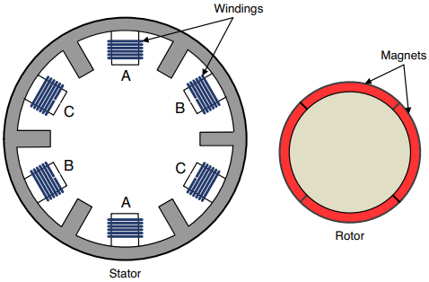
As shown in the figure, the structure of a BLDC is completely different from that of a brushed motor. There are multiple current-carrying wires, and they’re in the stator instead of the rotor. These wires wrap around iron cores, so they behave as electromagnets. We’ll refer to the BLDC’s electromagnets as windings .
The overall operation of a BLDC isn’t hard to understand. The controller delivers positive and negative current to different windings in a sequence, and the rotor spins to follow the change in current. As an analogy, the rotor is like a greyhound in a dog race, constantly following the mechanical rabbit as it runs around the track. The rest of this section goes into greater depth on three structural aspects of a BLDC: the windings, magnets, and slot/pole configuration.
Windings: In Figure 3.16 , the six windings are fixed into positions called slots. The controller governs the motor’s operation by delivering current to these windings. The process of delivering current to a winding is called energizing the winding. The windings’ names are important because windings with the same name are connected.
That is, both windings named A receive current at the same time, as do both windings named B and both windings named C. In this manner, the controller only has to deliver three inputs to the motor. For this reason, this BLDC is called a three-phase motor. More phases are possible, but most BLDCs are three-phase motors.
A BLDC’s windings are energized in a clockwise or counterclockwise manner. As current switches between the windings, the rotor turns at the same speed. Because the motor’s speed is synchronized with the changing current, BLDCs can be referred to as synchronous motors . The term synchronous is usually associated with AC motors, so it may seem surprising to see it used to describe a DC motor.
In fact, the structure of a BLDC is similar to that of a synchronous AC motor in many respects. The main difference between a BLDC and an AC motor is that the current delivered to a BLDC’s windings is constant for the duration of the pulse. In an AC motor, the current delivered to the windings is sinusoidal.
At low speeds, a BLDC’s rotor may align itself with the stator slots in such a way that it prefers to remain in place than continue rotating. This is called cogging, and it can cause the rotor to rotate in a jerky fashion. One solution is to use motors with slotless stators.
Slotless BLDCs require more windings due to the greater air gap between the rotor and stator, and are therefore more expensive than regular brushless motors.
Magnets: In a brushed motor, magnets are fixed to the stator. In a brushless motor, magnets are mounted on the surface of the rotor. The rotor in Figure 1 has four magnets, but it’s common to see BLDCs with many more. Each magnetic pole in the rotor is called a pole. In general, increasing the number of poles increases the torque. BLDC datasheets generally specify how many poles the motor has.
Slot/Pole Configuration: Researchers have spent a great deal of time studying how the number of poles and slots affects a motor’s operation.
In an integral slot motor, the number of slots is a multiple of the number of poles. In a fractional slot motor, the number of slots is not a multiple of the number of poles. To reduce cogging, fractional slot motors are generally preferred.
The motor depicted in Figure 1 is a fractional slot motor because the number of slots, six, isn’t a multiple of the number of poles, four.
On occasion, the slots of a brushless motor are referred to as stator poles and the magnets are referred to as magnet poles. A BLDC’s poles may be given as XN, YP, where X is the number of stator poles (slots) and Y is the number of magnet poles (magnets).
Inrunner and Outrunner BLDC Motors
BLDCs can be divided into two categories depending on the relative positions of the rotor and stator. If the rotor turns inside the stator, as illustrated in Figure 1, the motor is an inrunner. If the rotor turns outside the stator, it’s an outrunner. This section discusses both types.
Inrunners: Because the rotor turns inside the stator, an inrunner BLDC motor looks like a regular brushed motor. Judging by appearances, the main difference is that BLDCs have three inputs instead of two.
Many inrunner motors don’t have iron cores. This reduces the iron loss and increases efficiency, but it also significantly reduces the amount of torque the motor can exert. In addition, inrunner motors generally have a low number of poles (commonly only two). For these reasons, inrunner motors usually aren’t used to turn propellers without attached gearing.
To make up for their low torque, most inrunner motors turn at very high speeds. This can be seen by looking at their KV values, some of which get as high as 7,500 to 10,000 RPM/V.
Outrunners: On an outrunner motor, the rotor is positioned on the outside of the stator. In other words, the permanent magnets spin around the windings. Figure 2 presents the structure of an outrunner BLDC.
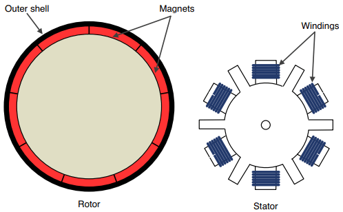
Because the magnets are on the outer shell, outrunners typically have more magnets than inrunner motors. The motor depicted in Figure 2 has nine poles, but it’s not uncommon to see outrunners with as many as 16.
Outrunner motors don’t spin as quickly as inrunners, and their KV values tend to be around 1,000 – 2,000 RPM/V. However, they produce significantly more torque. This is why outrunners are commonly employed to spin discs in CD/DVD players. Their high torque has also made them popular in the remote-controlled aircraft community.
Difference between inrunners and outrunners involves the motor’s shaft. For an inrunner motor, the shaft is connected to the internal rotor. For outrunners, the shaft is connected to the shell.
Controlling BLDCs
Brushless DC motors (BLDCs) are powered with timed pulses of electrical power. The number of inputs is determined by the motor’s number of phases. In general, it’s safe to assume that a BLDC receives three inputs. To control a BLDC properly, the pulses must be timed so that current is delivered when the rotor is in the right position.
To determine the rotor’s position, most BLDC circuits use one of two methods: They measure the back-EMF produced by the motor’s rotation or they read the rotor’s position using sensors built into the motor.
Control Signals and Inverters
A three-phase BLDC has three inputs that deliver current to the windings. At any time, one input will be set high (V+), one will be set low (V-), and one will be left floating. I’ll call these inputs A, B, and C. Figure 3 gives an idea how their signals change over time.
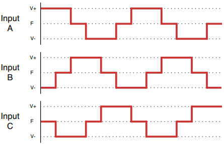
For a three-phase BLDC, there are only six unique phase states before they repeat. As the controller energizes the windings through these states, the rotor makes a complete rotation (360°). Therefore, each phase state corresponds to one-sixth of the complete turn, or 60°.
If the controller delivers more current, the motor will exert more torque as it rotates. If the pulses’ order and timing is reversed, the motor will turn in the reverse direction. For this reason, BLDC control circuits don’t require the H bridges needed to reverse brushed motors.
BLDCs receive power through special switching circuits called voltage source inverters, usually shortened to inverters .
Figure 4 shows what a MOSFET-based inverter looks like. Each transistor has a flyback diode to discharge current as needed.
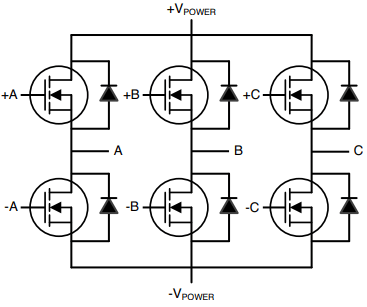
This circuit has six inputs (+A, -A, +B, -B, +C, and -C) that are connected to the controller. Each input is connected to the gate of a MOSFET. Each pair of inputs contributes to an output signal (A, B, or C) that delivers current to the BLDC’s windings.
If a positive input is high, the upper MOSFET conducts positive voltage to the corresponding output. If a negative input is high, the lower MOSFET conducts negative voltage to the corresponding output. For example, when the -C input is high, its MOSFET conducts -VPOWER to the C output, which is directed to the motor’s winding.
Sensored Control
Earlier, I compared the BLDC rotor following the stator’s windings to a greyhound chasing a mechanical rabbit around a track. No matter how quickly the greyhound runs, the rabbit must always be kept ahead of it.
The situation is similar for BLDCs. The controller must know the rotor’s orientation before it energizes the windings. Some motors have built-in sensors that identify the rotor’s orientation and/or speed. If this is the case, the control circuit can use sensored control. If the motor doesn’t have sensors, the control circuit must rely on sensorless control .
A motor’s sensors may use optical encoding, magnetic encoding, or variable reluctance, but the most common BLDC sensor is the Hall effect sensor. Many high-end BLDCs, such as those found in larger RC aircraft, have built-in Hall effect sensors.
When current flows through a conductor in the presence of a magnetic field, a voltage is generated that opposes the direction of the current. This is the Hall effect. The voltage is called the Hall voltage, VH, and it’s proportional to the product of the current and the magnetic field.
If a BLDC has Hall effect sensors, it will have additional electrical connections that enable the controller to read VH for each winding. With this information, the controller can determine how the magnetic field is oriented, and therefore how the rotor is oriented. No signal filtering or mathematical computation is necessary.
Sensored motor control is easier to implement and more reliable than sensorless control, but sensored BLDCs require additional circuitry, which means larger motors and higher cost.
Sensorless Control
A motor’s rotation produces a voltage called the back-EMF. Each winding in a three-phase BLDC produces its own back-EMF, and by measuring the three voltages, a controller can determine how the rotor is oriented.
This raises an important question: If the controller is sensorless, how does it measure back-EMF? The answer is simple. At any time, two of the BLDC’s phases are set to a voltage (one positive, one negative) and the third is left floating. The controller measures back-EMF by reading the voltage of the floating winding.
For example, when A is set to V+, B is set to V-, and C is floating, the controller reads the back-EMF of C. When C is set to +V and A is set to -V, the controller reads the back-EMF of B. In this manner, the controller can read the back-EMF of each winding, in turn.
For a BLDC, the back-EMF of each winding has the same approximate shape. As an example, Figure 5 depicts the back-EMF voltage across the B winding (solid line) relative to the input current (dashed line).
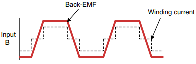
Back-EMF is proportional to the motor’s speed, so before the controller can measure back-EMF, the motor must already be rotating. Therefore, the controller must start the motor until its windings produce enough back-EMF to allow the controller to determine the rotor’s orientation. This can be confusing, so let me summarize the three steps of sensorless control:
- The controller delivers current to the motor’s windings to start rotation.
- The controller monitors the back-EMF until it can determine the rotor’s orientation.
- After the controller determines the rotor’s orientation, it uses this information to synchronize the pulses delivered to the motor’s windings.
One popular method of computing the rotor’s orientation involves integrating the back-EMF to determine when it equals zero. This is called zero-crossing detection, or ZCD. When the back-EMF in the floating winding equals zero, the rotor’s orientation can be readily obtained.
advantage of the ZCD method is that the computation is simple. However, the back-EMF signal must be filtered to remove noise and the method doesn’t work well at high speed. A controller relying on ZCD must limit the motor’s speed accordingly.
A more recent method of determining the rotor’s orientation makes use of extended Kalman filters (EKF). Kalman filtering requires a great deal of complex math, but unlike ZCD, this method isn’t affected by noise. Therefore, if the computation can be performed quickly, an EKF controller allows higher speed than a ZCD controller.
Sensorless control systems are simple to manufacture and cost-effective because no additional hardware is needed. However, a startup period is required so that the controller can measure back-EMF. Further, the process of computing the rotor’s orientation places a limit on the motor’s maximum speed.
There’s one last point I want to mention. As shown in Figure 5, the back-EMF of a BLDC winding is approximately trapezoidal in shape. For this reason, BLDCs are frequently referred to as trapezoidal motors. In contrast, synchronous AC motors are referred to as sinusoidal motors because the back-EMF in their windings is sinusoidal.