Components of Microcontroller
Microcontrollers are hidden inside almost every product or device with which its user can interact. In fact, any device that has a remote control or has an LED/LCD screen and a keypad has an embedded microcontroller.
Some common products where one is sure to find the use of a microcontroller include automobiles, microwave ovens, TVs, VCRs, high-end stereo systems, camcorders, digital cameras, washing machines, laser printers, telephone sets with caller ID facility, mobile phones, refrigerators and so on.
Introduction to the Microcontroller
The microcontroller may be considered as a specialized computer-on-a-chip or a single-chip computer. The word ‘micro’ suggests that the device is small, and the word ‘controller’ suggests that the device may be used to control one or more functions of objects, processes or events. It is also called an embedded controller as microcontrollers are often embedded in the device or system that they control.
The microcontroller contains a simplified processor, some memory (RAM and ROM), I/O ports and peripheral devices such as counters/timers, analogue-to-digital converters, etc., all integrated on a single chip. It is this feature of the processor and peripheral components available on a single chip that distinguishes it from a microprocessor-based system.
A microprocessor is nothing but a processing unit with some general-purpose registers. A microprocessor-based system also has RAM, ROM, I/O ports and other peripheral devices to make it a complete functional unit, but all these components are external to the microprocessor chip.
While a microprocessor-based system is a general-purpose system that may be programmed to do any of the large number of functions it is capable of doing, microcontrollers are dedicated to one task and run one specific program. This program is stored in ROM and generally does not change.
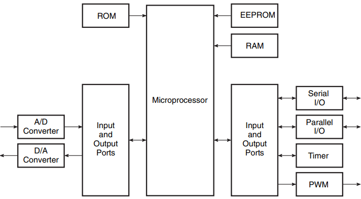
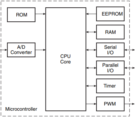
Figure 1 further illustrates the basic difference between a microprocessor-based system and a microcontroller. As is evident from the two block schematics shown in the figure, while a microprocessor-based system needs additional chips to make it a functional unit, in a microcontroller the functions of all these additional chips are integrated on the same chip.
Applications of Microcontroller
Microcontrollers are embedded inside a surprisingly large number of product categories including automobiles, entertainment and consumer products, test and measurement equipment and desktop computers, to name some prominent ones. Any device or system that measures, stores, controls, calculates or displays information is sure to have an embedded microcontroller as a part of the device or system.
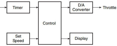
- In automobiles, one or more microcontrollers may be used for engine control, car cruise control (Fig. 2), antilock brakes and so on.
- Test and measurement equipment such as signal generators, multimeters, frequency counters, oscilloscopes, etc., make use of microcontrollers to add features such as the ability to store measurements, to display messages and waveforms and to create and store user routines.
- In desktop computers, microcontrollers are used in peripheral devices such as keyboards, printers, modems, etc.
- Consumer and entertainment products such as TVs, video recorders, camcorders, microwave ovens, washing machines, telephones with caller ID facility, cellular phones, air conditioners, refrigerators and many more products make extensive use of microcontrollers to add new control and functional features.
Inside the Microcontroller
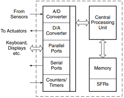
Figure 3 shows the block schematic arrangement of various components of a microcontroller. As outlined earlier, a microcontroller is an integrated chip with an on-chip CPU, memory, I/O ports and some peripheral devices to make a complete functional unit.
A typical microcontroller as depicted in Fig. 4 has the following components:
- a central processing unit (CPU),
- a random access memory (RAM),
- a read only memory (ROM),
- special-function registers and
- peripheral components including serial and/or parallel ports, timers and counters, analogue-to-digital (A/D) converters and digital-to-analogue (D/A) converters.
Central Processing Unit (CPU)
The central processing unit processes the program. It executes the instructions stored in the program memory pointed to by the program counter in synchronization with the clock signal. The processor complexity could vary from simple eight-bit processors to sophisticated 32-bit or even 64-bit processors.
Some common microcontrollers using eight-bit processors include 68HC11 (Freescale Semiconductor – earlier part of Motorola), the 80C51 family of microcontrollers (Intel and Dallas Semiconductor), Zilog-eZ8 and Zilog-eZ80 (Zilog) and XC800 (Infineon).
Examples of microcontrollers using 16-bit processors include the 8096 family (Intel), 68HC12 and 68HC16 (Freescale Semiconductor), the F2MC family (Fujitsu) and the XC166 family (Infineon).
Examples of microcontrollers using 32- bit processors include 683XX, MPC 860 (PowerQUICC), MPC 8240/8250 (PowerQUICC-II) and MPC 8540/8555/8560 (PowerQUICC-III) (all from Freescale Semiconductor), the TRICORE family (Infineon) and the FR/FR-V family (Fujitsu).
Random Access Memory (RAM)
RAM is used to hold intermediate results and other temporary data during the execution of the program. Typically, microcontrollers have a few hundreds of bytes of RAM. As an example, microcontroller type numbers 8XC51/80C31, 8XC52/80C32 and 68HC12 respectively have 128, 256 and 1024 bytes of RAM.
Read Only Memory (ROM)
ROM holds the program instructions and the constant data. Microcontrollers use one or more of the following memory types for this purpose:
- ROM (mask-programmed ROM),
- PROM (one-time programmable ROM, which is not field programmable),
- EPROM (field programmable and usually UV erasable),
- EEPROM (field programmable, electrically erasable, byte erasable) and flash (similar to EEPROM technology).
Microcontroller type numbers 8XC51, 8XC51FA and 8XC52 have 4K, 8K and 16K of ROM. As another example, the 68HC12 16-bit microcontroller has 32K of flash EEPROM, 768 bytes of EEPROM and 2K of erase-protected boot block.
Special-Function Registers
Special-function registers control various functions of a microcontroller. There are two categories of these registers. The first type includes those registers that are wired into the CPU and do not necessarily form part of addressable memory. These registers are used to control program flow and arithmetic functions. Examples include status register, program counter, stack pointer, etc.
These registers are, however, taken care of by compilers of high-level languages, and therefore programmers of high-level languages such as C, Pascal, etc., do not need to worry about them.
The other category of registers is the one that is required by peripheral components. The contents of these registers could, for instance, set a timer or enable serial communication and so on. As an example, special-function registers available on the 80C51 family of microcontrollers (80C51, 87C51, 80C31) include a program counter, stack pointer, RAM address register, program address register and PC incrementer.
Peripheral Components of Microcontroller
Peripheral components such as analogue-to-digital converters, I/O ports, timers and counters, etc., are available on the majority of microcontrollers. These components perform functions as suggested by their respective names.
In addition to these, microcontrollers intended for some specific or relatively more complex functions come with many more on-chip peripherals. Some of the common ones include the pulse width modulator, serial communication interface (SCI), serial peripheral interface (SPI), interintegrated circuit (I2C) two-wire communication interface, RS 232 (UART) port, infrared port (IrDA), USB port, controller area network (CAN) and local interconnect network (LIN). These peripheral devices are briefly described in the following paragraphs.
Analogue-to-Digital Converters
Analogue-to-digital and digital-to-analogue converters provide an interface with analogue devices. For example, the analogue-to-digital converter provides an interface between the microcontroller and the sensors that produce analogue electrical equivalents of the actual physical parameters to be controlled.
The digital-to-analogue converter, on the other hand, provides an interface between the microcontroller and the actuators that provide the control function. As an example, both 68HC11 and 68HC12 from Freescale Semiconductor have eight-channel, eight-bit analogue-to-digital converters.
The digital-to-analogue converter function in microcontrollers is provided by a combination of pulse width modulator (PWM) followed by a filter. As an example, 68HC12 has an on-chip 16-bit/two-channel PWM.
I/O Ports of Microcontroller
I/O ports provide an interface between the microcontroller and the peripheral I/O devices such as the keyboard, display, etc. The 80C51 family of microcontrollers has four eight-bit I/O ports. Microcontroller 68HC11 offers 38 general-purpose I/O pins including 16 bidirectional I/O pins, 11 input-only pins and 11 output-only pins.
Counters/Timers
Counters/timers usually perform the following three functions. They are used to keep time and/or measure the time interval between events, count the number of events and generate baud rates for the serial ports.
Microcontroller 68HC11 has a 16-bit timer system comprising three input capture channels, four output compare channels and one additional channel that can be configured as either an input or an output channel. Another popular microcontroller type number, PIC 16F84, has an eight-bit timer/counter with an eight-bit prescaler.
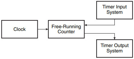
Figure 4 shows a generalized block schematic representation of the timer subsystem of a microcontroller. The clock signal controls all timing activities of the microcontroller. The counter is used both to capture external timing events (accomplished by the timer input block) and to generate timing events for external devices (accomplished by the timer output block).
While the former process is typically used to measure the frequency and time interval of periodic signals, the latter generates control signals for external devices. It may be mentioned here that a timing event to be captured or generated is nothing but a change in logic status on one of the microcontroller I/O pins configured as an input pin if the event is to be captured and as an output pin if it is to be generated.
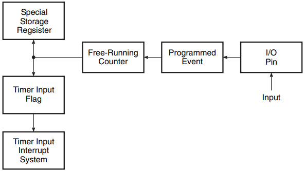
Figure 5 shows a block schematic arrangement of the timer input block of Fig. 4. As shown in the figure, the counter captures the input time event in the form of its contents at the time of occurrence of the event. In fact, the counter captures the relative time of the event as the counter is free running. Absolute timing values can be computed from the relative system clock values.
As an example, consider a microcontroller with a 10 MHz clock and a 16-bit counter/timer subsystem. This counter will take 6.5536 ms to count from 0000 to FFFF (hex notation). Let us assume that it is desired to find the frequency of a periodic signal whose successive rising or falling edges are observed to occur at 0010 and 0150. 0010 and 0150 respectively correspond to 16 and 336 in decimal. Therefore, the time interval between two successive edges equals 320 × 0.1 = 32 s. The signal frequency is therefore (1/32) MHz = 31.25 kHz.
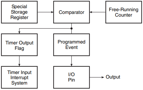
Figure 6 shows a block schematic arrangement of the timer output block of Fig. 4. The diagram is self-explanatory.
Again, free-running counter values can be used to synchronize the time of the desired logic state changes on the output pin. This feature can also be used to generate a periodic pulse or a periodic signal of any desired duty cycle. For timer input and output operations, the microcontroller needs to set up some special registers.
For timer input operation, as shown in Fig. 5, registers are required to program the event (logic HIGH or logic LOW), configure the physical I/O pin as an input pin and also set up parameters for the related interrupt, if used. Another register is used to capture the counter value at the time of occurrence of the event.
For time output operation, as shown in Fig. 6, the physical I/O pin is to be configured as an output pin, the event is to be programmed and the timing value is to be set in the special register to tell when the programmed event should appear on the output pin. The output timer system also has an associated interrupt that can be utilized if needed.
Serial Communication Interfaces
There are two types of serial communication interface, namely the asynchronous communication interface and the synchronous communication interface.
The asynchronous communication interface uses a start and stop bit protocol to synchronize the transmitter and receiver. Start and stop bits are embedded in each data byte. Compared with the synchronous communication interface, it offers lower data transmission rates. It is also referred to as the universal asynchronous receiver/transmitter (UART) or the serial communication interface (SCI).
The synchronous communication interface uses a synchronized clock to transmit and receive each bit. Synchronization of transmitter and receiver clocks is usually accomplished by using an additional clock line linking the transmitter and the receiver. It is not recommended for long distance communication. It is also referred to as the serial peripheral interface (SPI).
Microcontroller 68HC11 offers an asynchronous non-return-to-zero serial communication interface and also a synchronous serial peripheral interface. The 80C51 family of microcontrollers offers a full duplex-enhanced UART interface.
Since a large number of peripheral devices are equipped to communicate with an RS-232-compatible interface, which is a serial interface standard that specifies the different aspects, including electrical, mechanical, functional and procedural specifications, a variety of chips are available to translate microcontroller signals to RS-232-compatible signals. These chips are equipped to provide interfacing for a two-way communication system.
Interintegrated Circuit (I2C) Bus
The interintegrated circuit (I2C) bus is a two-wire, low- to-medium-speed serial communication interface developed by Philips Semiconductors in the early 1980s for chip-to-chip communications. The two wires in the I2C bus are called clock (SCL) and data (SDA). The SDA wire carries data, while the SCL wire synchronizes the transmitter and receiver during data transfer.
It is a proven industry-standard communication protocol used in a variety of electronic products, which is particularly facilitated by its low cost and powerful features.
It is supported by a large number of semiconductor and system manufacturers who offer a variety of electronic products including input and output devices, different types of sensor, memory devices, displays, data entry devices, etc.
Some of the important features offered by I2C devices are briefly described in the following paragraphs.
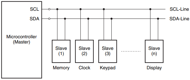
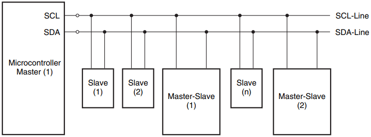
I2C devices offer master–slave hierarchy. These are classified as either master (the device that initiates the message) or slave (the device that responds to the message). The device can be either master only or slave only or can be switched between master and slave depending upon the application requirement. One possible master–slave configuration is the one where one master (e.g. a microcontroller) is connected to many chips configured as slaves, as shown in Fig. 7.
Each of the I2C slave devices is identifiable by a unique address. When the master device sends a message, it includes the address of the intended slave device at the beginning of the message.
The I2C interface also supports multiple master devices at the same time. The bus has a special feature that allows it to resolve signal conflicts should two or more master devices try to talk on the bus at the same time.
A master I2C device that detects the conflict, called arbitration loss, terminates its use of the bus, thus allowing the message sent by another master to cross the bus unharmed. Figure 8 shows one such multi-master support arrangement.
Controller Area Network (CAN) Bus
The controller area network (CAN) bus is a rugged serial communication interface used in a broad range of embedded as well as automation control applications. It was introduced by Bosch in 1986 for in-vehicle networks in automobiles.
The CAN protocol was internationally standardized in 1993 as ISO-11898-1 and comprises the data link layer of the seven-layer ISO/OSI reference model. The protocol provides two communication services, namely data frame transmission (sending of a message) and remote transmission request (requesting of a message). All other services such as error signalling, automatic retransmission of erroneous frames, etc., are performed by CAN chips. Some of the important features of the CAN protocol include the following.
- It provides a multi-master hierarchy. This allows the user to build intelligent and redundant systems.
- It uses the broadcast communication method. The sender of a message transmits to all devices connected to the bus. All devices read the message and decode it if it is intended for them. This feature guarantees data integrity. Data integrity is also ensured by error detection mechanisms and automatic retransmission of faulty messages.
- CAN protocol provides low-speed fault-tolerant transmission at a rate of 125 kbps up to a distance of 40 m, which can function over one wire if there is a short. Transmission without fault tolerance is provided at a rate of 1 Mbps up to a distance of 40 m. Transmission rates of 50 kbps are achievable up to a distance of 1 km.
Local Interconnect Network (LIN) Bus
The local interconnect network (LIN) bus is a broadcast serial network that is used as a low-cost sub network of a CAN bus to integrate intelligent sensors or actuators in modern automobiles. It comprises one master (typically a moderately powerful microcontroller) and up to 16 slaves (less powerful, cheaper microcontrollers or ASICs).
It does not offer a collision detection feature and therefore all messages are initiated by the master with at the most one slave replying to a given message identifier. Multiple such LIN networks may all be linked to a CAN upper layer network through their respective masters.
Related Posts
- Logic Gates
- Significance & Types of Logic Family
- Characteristics Parameters of Logic Families
- TTL Logic Family
- ECL Logic Family
- CMOS Logic Family
- Interfacing of Logic Families
- Microcontroller Architecture
- Components of Microcontroller
- Interfacing Devices with Microcontroller
- IC Based Multivibrator Circuits
- Astable, Monostable & Bistable Multivibrator
- Logic Analyser
- Types of Oscilloscope
- Frequency Synthesizers
- Frequency Counter