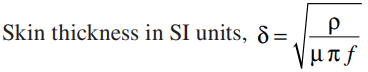
A steady direct current flowing through the conductors is uniformly distributed over the whole cross-section of the conductor. However, an alternating current flowing through the conductor does not distribute uniformly, rather it tends to concentrate near the surface of the conductor as shown in the figure. This is known as skin effect in transmission line.
Skin Effect in Transmission Line
Thus, the tendency of an alternating current to concentrate near the surface of the conductor is known as skin effect in transmission line.
Due to skin effect, the effective area of the cross-section of the conductor through which current is to flow is reduced. This increases the resistance of conductor when carrying an alternating current. The cause of skin effect in transmission line is explained below:
Generally, a stranded conductor is used and each strand carries a small part of the current. The each conductor strand, near the center, is surrounded by a greater magnetic flux and hence has larger inductance than that strand near the surface. The high reactance (opposition) of inner stands restricts the flow of current in the center and causes it to flow near the surface of the conductor which produces skin effect.
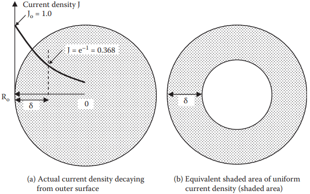
The higher the frequency, the thinner the skin depth, which is given by
Where ρ = electrical conductivity of wire, μ = magnetic permeability of flux medium, and f = frequency, all in SI units.
For copper at typical working temperature, the skin depth is approximately 10 mm (0.394 inch) at 60 Hz, 3.87 mm (0.152 in.) at 400 Hz, 0.5 mm (0.020 in.) at 20 kHz, and 0.25 mm (0.010 in.) at 100 kHz.
Thinner skin with concentrated current means less cross section area for the current and proportionally higher conductor resistance. For this reason, the ac resistance is always higher than the dc resistance depending on the frequency.
For example, a 5 mm (0.20 inch) thick bus bar would have the ratio Rac/Rdc = 1.1 at 60 Hz, 1.32 at 400 Hz, and 20 at 100 kHz.
How to Reduce Skin Effect in Transmission Line
The skin effect in transmission line depends upon the following factors:
- Nature of material.
- The diameter of wire – The skin effect increases with the diameter of wire.
- The shape of wire – The skin effect is lesser for stranded conductor than the solid conductor.
- Frequency – The skin effect increases with the increase in frequency. When the frequency is zero (DC), there is no inductance and hence the current is uniformly distributed over the entire cross-section of the conductor. No skin effect. It is worthwhile to mention here that skin effect is negligible when the frequency is less (below 50 Hz) and conductor diameter is small (below 1 cm).
By utilizing this information properly, skin effect can be reduced considerably..
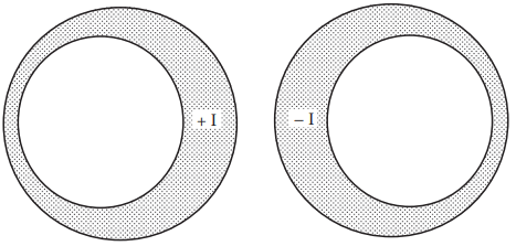
Proximity Effect in Transmission Lines
In the skin effect, the flux set up in the conductor itself was considered and it was assumed that there is no other current carrying conductor nearby. This flux produces a nonuniform distribution of current in the conductor called skin effect.
However, in the transmission lines, there are (one or two) current carrying conductors placed nearby and their magnetic flux links with the conductor under consideration. The effect of this flux is more in the nearer half of the conductor than the farther.
When the conductors carry currents in the opposite directions the fields set-up will tend to cause an increase in the current density in the adjacent portions whereas when the currents are in the same directions the current density is increased in the farther parts of the conductor. This effects the distribution of current in the conductor.
Thus, the flux set up by the nearby current carrying conductor effects the distribution of current in the conductor. This effect is called proximity effect in transmission lines. Hence, the proximity effect in transmission lines also results in the increase in resistance of the conductor.
Transposition of Conductors in Transmission Lines
It has already been discussed that when conductors of a three-phase overhead line have symmetrically spaced the inductance and capacitance of the three phases are identical.
However, due to mechanical considerations, it is often desirable to space the conductors irregularly (unsymmetrical spacing). The inductance and capacitance of each phase will be different when conductors of a three-phase line are spaced irregularly. Rather, the apparent resistance of the conductors is also affected on account of the transfer of power between the phases, which occurs due to mutual inductance (proximity effect).
Thus, the result of this irregular spacing is that all the transmission line constants are different in three phases of the line. This makes different voltage drops in the three phases and results in different line voltages at the receiving end. This unbalancing effect on account of irregular spacing of conductors can be avoided by changing the position of conductors at regular distances. This is called transposition of conductors in transmission lines.
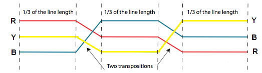
The process of changing the positions of the conductors (spaced unsymmetrically) of a three-phase overhead line at regular distances in order to make the transmission line constants of the three phases symmetrical, is called transposition of conductors in transmission lines.
In practice, the conductors have so transposed that each of them attains all the three positions for one-third of the total length of the line. The position of the three conductors is changed after every one-third of the length of the line.
Thus for the first one-third length of the line, the position of the conductors is RYB, then over the next one-third the position is BRY and over the remaining one-third, the position is YBR. The transposition of conductors also reduces the inductive interference with the nearby communication circuits and thus reduces the disturbances.
Advantages of transposition of conductors in transmission lines
Transposition of overhead line conductors has the following advantages:
- It makes the transmission line constants of the three phases symmetrical which result in equal voltage drops in three phases. Hence equal line voltages are available at the receiving end.
- It reduces the disturbances in the neighbouring communication circuits.
Skin Effect in Transmission Line | MCQ
1. In a transmission line the distributed constants are
(a) resistance and shunt conductance only.
(b) resistance and inductance only.
(c) resistance, inductance and capacitance only.
(d) resistance, inductance, capacitance and shunt conductance.
Answer: (d) resistance, inductance, capacitance and shunt conductance.
2. Skin effect depends upon
(a) x-section of conductor.
(b) supply frequency.
(c) permeability of conductor material.
(d) all of the above.
Answer: (d) all of the above.
3. Skin effect in transmission line is due to
(a) supply frequency.
(b) self inductance of conductor.
(c) high sensitivity of material in the centre.
(d) both (a) and (b).
Answer: (d) both (a) and (b).
4. The effective resistance of a conductor will be the same as ohmic resistance when
(a) voltage is low.
(b) current is true sinusoidal.
(c) current is uniformly distributed in the x-section of the conductor.
Answer: (c) current is uniformly distributed in the x-section of the conductor.
5. When an alternating current flows through a conductor
(a) entire current passes through the core of the conductor.
(b) portion of conductor near the surface carries more current in comparison to the core.
(c) current remains uniformly distributed over the whole x-section of the conductor.
(d) portion of conductor near the surface carries less current in comparison to the core.
Answer: (b) portion of conductor near the surface carries more current in comparison to the core.
6. The conductor carries more current on the surface in comparison to its core. This phenomenon is called the
(a) skin effect.
(c) Ferranti effect.
(b) corona.
(d) Lenz’s effect.
Answer: (a) skin effect.
7. Increasing the frequency of transmission line will
(a) increase shunt reactance.
(b) decrease line resistance.
(c) increase line resistance.
(d) decrease series reactance.
Answer: (c) increase line resistance.
8. Skin effect exists in
(a) cable carrying dc current.
(b) dc transmission line only.
(c) ac transmission line only.
(d) dc as well as ac transmission lines.
Answer: (c) ac transmission line only.
9. Skin effect in a conductor becomes more pronounced
(a) at higher frequency.
(b) at lower frequency.
(c) at dc.
Answer: (a) at higher frequency.
10. The skin effect in conductor results in
(a) increases in its dc resistance.
(b) decrease in its ac resistance.
(c) increase in its ac resistance.
Answer: (c) increase in its ac resistance.
11. Skin effect
(a) increases the effective resistance and effective internal reactance.
(b) reduces the effective resistance and effective internal reactance.
(c) increases the effective resistance but reduces the effective internal reactance.
(d) reduces the effective resistance but increases the effective internal reactance.
Answer: (c) increases the effective resistance but reduces the effective internal reactance.
12. The skin effect of a conductor reduces with the increase in
(a) supply frequency.
(b) resistivity of the conductor material.
(c) x-section of conductor.
(d) permeability of conductor material.
Answer: (b) resistivity of the conductor material.
13. Skin effect in conductor is proportional to
(a) (diameter of conductor)1/2.
(b) diameter of conductor.
(c) (diameter of conductor)2.
(d) (diameter of conductor)4.
Answer: (c) (diameter of conductor)2.
14. In order to reduce the skin effect at UHF
(a) copper tubes with silver plating are used.
(b) copper rods with silver plating are used.
(c) anodized conductors are used.
(d) painted conductors are used.
Answer: (a) copper tubes with silver plating are used.
Related Posts
- Types of Poles in Transmission Line
- Overhead Line Insulators
- Voltage Distribution Over Suspension Insulator String
- Kelvin’s Law in Power System
- Skin Effect and Proximity Effect in Transmission Line
- Voltage Regulation & Efficiency of Transmission Line
- Corona Effect in Transmission Lines
© https://www.yourelectricalguide.com/ skin effect in transmission line.