Hi friends,
In this article, I am going to discuss the thermocouple instrument working principle, its types and applications. So let us start with our topic.
When two metals of different work functions are placed together, a voltage is generated at the junction. This generated voltage is proportional to the temperature and this junction is known as Thermocouple.
Thermocouple Instrument Working Principle
In a thermocouple type instrument, the electrical current to be measured is passed through a heater element. And the heat produced by the heater element is sensed by a thermocouple, as a result, an EMF is generated at its terminals which can be measured with the help of a PMMC instrument.
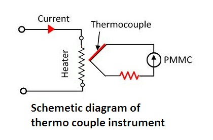
The EMF generated is proportional to the temperature and hence to the RMS value of the current passing through the heater. The scale of the PMMC instrument can be calibrated to read the current passing through the heater. This is the basic thermocouple instrument working principle.
These instruments can be used for both AC as well as DC applications. These instruments are very useful and accurate to measure current and voltages at very high frequencies. The thermocouple type instruments consist of the following major parts:
- thermo-electric element and
- indicating instrument
The EMF produced in thermocouple type instruments is DC in nature and is of the order of a few mV. Therefore, for the purpose of indication permanent magnet moving coil (PMMC) type instruments are used since they have a high degree of accuracy and sensitivity.
This instrument has a nearly “square law response”. Thus if we use an ordinary permanent magnet moving coil instrument having a uniform air gap, the scale will not be uniform.
The scale shape may be modified by suitably shaping the pole faces of the permanent magnet. To obtain a nearly uniform scale, the air gap is made non-uniform in such a way that flux density diminishes as the coil moves upscale.
Thermo-electric Element
The thermoelectric elements consist of a heater wire through which current to be measured is passed. The other part of the thermoelectric element is the thermocouple which develops an EMF proportional to the difference between the hot junction (heater in this case) and the cold reference junction.
The most important application of thermocouple type instruments is for the measurement of current and voltages at high frequencies, and therefore, the heater elements of such instruments should be free from skin effect.
The skin effect refers to a condition where at high frequencies the current is forced to pass through the outer surface of the conductor as the inductance and consequently the reactance of the inner parts of the conductor is much larger than that of the outer parts.
This increases the resistance of the conductor (since the current passes only through the outer part i.e. skin of the conductor and not through the inner part of the conductor whose reactance is higher than the outer part of the conductor).
In order to reduce the skin effect, the heater wires are designed with a small area of cross-section. In fact, in order to minimize the skin effect, a very fine wire of non-magnetic material having a very high resistivity is used for heater elements.
Types of Thermoelectric Elements
The main types of thermoelectric elements used in thermocouple instruments are as under:
Contact Type Thermo Electric Element
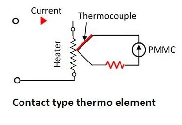
The contact type thermoelectric element has a separate heater wire and the thermocouple has one junction (hot junction) in contact with the heater wire. The working of the contact type thermoelectric element is as follows:
- Electrical energy is converted to the thermal energy in the heater element. Most of the heat energy is dissipated away and a portion of it is transferred to the hot junction.
- The heat energy transferred to the hot junction is converted back to electrical energy by Seebeck effect.
- The output of the thermocouple is connected to a permanent magnet moving coil instrument.
- A portion of the electrical energy in the thermocouple circuit is converted to mechanical energy in deflecting the pointer and is stored as potential energy in the springs of the instrument.
The overall efficiency of the system is very low, of the order of a few hundredths of a percent under most favorable circumstances. This means that the power consumption of the instrument is relatively high and a sensitive DC instrument has to be used as an indicating element.
Non-contact Type Thermoelectric Element
In the non-contact type thermoelectric element, there is no electric contact between the heating element and the thermocouple, the two are separated by electrical insulation. The heat is conducted from heater to junction across the insulation. This makes the instrument sluggish and less sensitive than the contact type.
However, the separation between the heater and the thermocouple becomes essential for measurement of currents in circuits operated at potentials considerably above the ground potential.
Vacuum Type Thermoelectric Element
In a very low-range thermocouple instrument, the power absorption is very low. In order to attain a required output, we have to increase the efficiency and sensitivity of the thermoelectric element.
This is done by enclosing both the heater and thermocouple assembly in a glass tube which is then evacuated. The efficiency is increased because there is no cooling of the heater due to convection air currents.
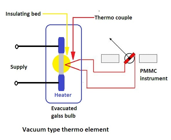
Figure shows a vacuum type thermo-electric element, where the heater element and the thereto-couple junction are electrically isolated from each other by a bead of insulating material. This is done to minimize the effects of capacitance between the thermocouple and the rest of the circuit at high frequencies.
The insulation creates a very small capacitance between the isolated circuits and is in series with the capacitance from the instrument to the ground or to other parts of the circuit. This reduces the capacitive currents which might otherwise be diverted through part of the heater element and produce errors in indication.
The capacitive currents may be a considerable part of the total current being measured if the instrument is used for measurement of very small currents.
With the advent of new materials, it is now possible to use materials for bead which have very high thermal conductivities. These instruments are very sensitive and have the same response as the contact types for currents up to 100 mA.
Another advantage of vacuum type is that the heater element can be operated at much higher temperatures. Vacuum type thermocouples may the used in the range 2 mA to 500 mA. Vacuum thermocouples are suitable for current measurements at frequencies up to 100 MHz or more depending on size and resistivity of wire.
For voltage measurements, very great difficulties are encountered in constructing suitable series resistors for the high-frequency range. Voltmeters with resistors of usual type are used up to 10 kHz. Special multipliers for low voltages permit measurements at frequencies up to 100 MHz.
Bridge Type Thermoelectric Elements
No heater element is used in this case; instead, the current to be measured passes directly through the thermocouples and raises their temperature proportional to I2R.
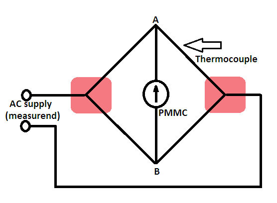
The thermocouples are connected as shown in Figure so that the resultant thermal EMFs give rise to a DC potential difference between A and B. No AC current can flow through the instrument as the bridge is balanced by keeping equal resistance for four arms.
This construction gives a greater output than that is given by a single thermocouple used in vacuum thereby giving a greater sensitivity and can withstand more mechanical shocks and overloads.
Bridge type elements are made with AC ratings from 100 mA to 1 A. The voltage available may be as much as 25 mV.
Advantages of Thermocouple Instruments
(i) The thermocouple instruments correctly indicate the RMS value of voltage or current irrespective of the waveform. The movement may be converted to a voltmeter by using multiplier resistance and a low current thermocouple. Thermo-couple voltmeters are available in ranges up to 500 V with sensitivities of 100 — 500 Ω/V.
(ii) These instruments are not affected by stray magnetic fields.
(iii) These instruments are free from frequency errors and hence they can be used over a very wide frequency range. In fact, they are primarily designed for current measurements at high frequencies.
In this application, they are superior to any other type of instrument both in accuracy and frequency range. Their accuracy can be as high as 1% for frequencies up to 50 MHz. Above this frequency the effective resistance of heater wire is increased on account of skin effect, thereby reducing the accuracy.
Tubular designs are used for heater wire above 3 A to reduce errors on account of skin effect produced by high frequencies. For small currents up to 3 A, the heater wire is solid and very thin.
(iv) These instruments can measure currents in the range of 0.5 to 20 A. For higher currents, the heater element is usually situated outside the instrument case. For lower currents, a bridge type arrangement is used.
(v) These instruments have high sensitivity.
(vi) They are very useful when used as transfer instruments to calibrate DC instruments by potentiometer and standard cell.
Disadvantages of Thermocouple Instruments
At normal rated current, the heater attains a temperature of 300°C. If we pass twice the rated current the heater would give a temperature of nearly 4 times the normal temperature, i.e., 1200°C. It is obvious that the square law rate will bring the heater to nearly its burn out temperature.
Thus it is very essential to protect the heater against damaging overloads. The fuses do not provide any protection as due to overload the heater wire may burn out before the fuse blows out.
Thus the overload capacity of a thermocouple type instrument is small as compared with other instruments and is about 150 percent of the full-scale current.
Thanks for reading about thermocouple instrument working principle .
Related Posts
- Construction and Working of Moving Iron Instruments
- Construction and Working of Dynamometer Type Wattmeter
- Construction and Working of Megger
- Construction and Working of Megger Earth Tester
- Construction and Working of Power Factor Meter
- Construction and Working of Resonance Type Frequency Meter
- Construction and Working of Analog Frequency Meter
- Construction and Working of Thermocouple Instruments
- Construction and Working of Lux Meter
- Construction and Working of Electrostatic Voltmeter
© www.yourelectricalguide.com/ thermocouple instrument working principle.