The superposition theorem is a method that allows us to determine the current through or the voltage across any resistor or branch in a network. The advantage of using this approach instead of mesh analysis or nodal analysis is that it is not necessary to use determinants or matrix algebra to analyze a given circuit.
The theorem states the that “The total current through or voltage across a resistor or branch may be determined by summing the effects due to each independent source.”
In order to apply the superposition theorem it is necessary to remove all sources other than the one being examined. In order to “zero” a voltage source, we replace it with a short circuit, since the voltage across a short circuit is zero volts.
A current source is zeroed by replacing it with an open circuit, since the current through an open circuit is zero amps.
It should be noted that the superposition theorem does not apply to power.
Superposition Theorem Examples
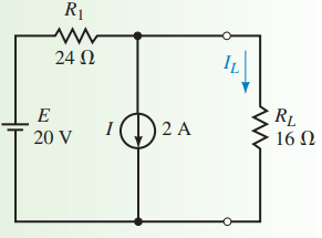
Determine the current in the load resistor, RL of Figure 1
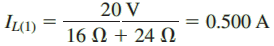
Solution: We first determine the current through RL due to the voltage source by removing the current source and replacing in with an open circuit (zero amps) as shown in Figure 2. The resulting current through RL is determined from Ohm’s law as
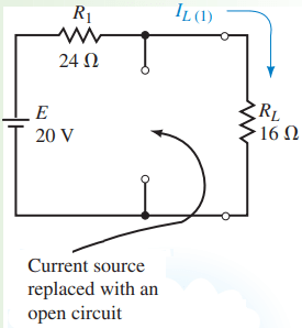
Next, we determine the current through RL due to the current source by removing the voltage source and replacing it with a short circuit (zero volts) as shown in Figure 3.
The resulting current through RL is found with the current divider rule as
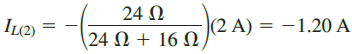
The resultant current through RL is found by applying the superposition theorem:
IL = 0.5 A – 1.2 A = – 0.700 A
The negative sign indicates that the current through RL is opposite to the assumed reference direction. Consequently, the current through RL will, in fact, be upward with a magnitude of 0.7 A.
The superposition theorem may also be used to determine the voltage across any component or branch within the circuit.
Example: Determine the voltage drop across the resistor R2 of the circuit shown in Figure 4.
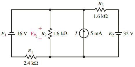
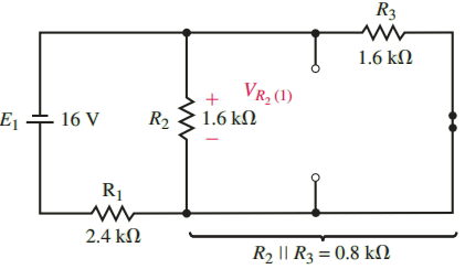
Solution: Since this circuit has three separate sources, it is necessary to determine the voltage across R2 due to each individual source. First, we consider the voltage across R2 due to the 16 V source as shown in Figure 5.
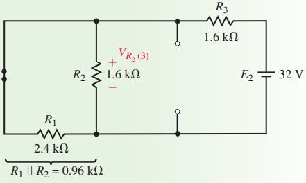
The voltage across R2 will be the same as the voltage across the parallel combination of R2||R3 = 0.8 k Ω. Therefore,
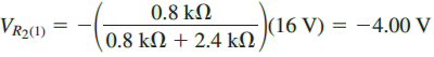
The negative sign in the preceding calculation simply indicates that the voltage across the resistor due to the first source is opposite to the assumed reference polarity.
Next, we consider the current source. The resulting circuit is shown in Figure 6. From this circuit, you can observe that the total resistance “seen” by the current source is
RT = R1||R2||R3 = 0.6 kΩ
The resulting voltage across R2 is
VR2(2) = 0.6 * 5 = 3.00 V
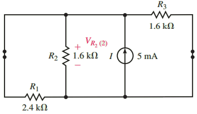
Finally, the voltage due to the 32 V source is found by analyzing the circuit of Figure 7. The voltage across R2 is
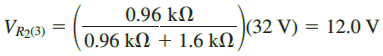
By superposition, the resulting voltage is
VR2 = 4.0 V + 3.0 V + 12.0 V = 11.0 V
Thanks for reading about “superposition theorem examples.”