Instrument Transformers
Instrument transformers are used for metering and protection in a power system. Electrical measurements and relaying decisions in a power system are made based on the current and voltage obtained from the system.
Relays work with smaller magnitudes of these signals. Real life currents and voltages thus have to be scaled to lower levels. This job is done by current and voltage transformers also known as instrument transformers.
They also electrically isolate the relaying system from the power equipment and working personnel.
Current Transformer
Current transformers (CTs) are extensively used in power system for power measuring circuits. CTs are generally used in panel boards in substations or grid station to measure the high valued bus bar currents. These are also used in combination with the relays for protection purposes.
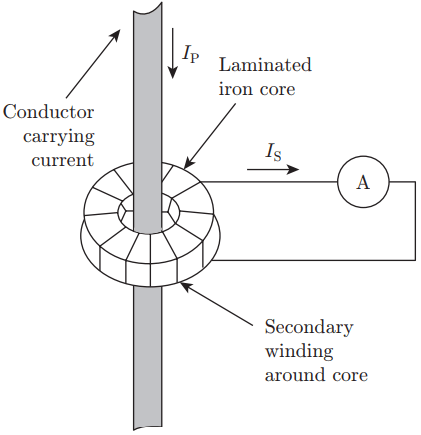
Current transformer can measure high currents in a conductor. The conductor carrying high current passes through circular and laminated iron core of the transformer. The conductor is the single turn primary winding.
The secondary winding will constitute of large number of turns of wire wound around this circular core.
The secondary current (IS) in turn is reduced to a lower value than the higher valued primary current (IP) as the secondary voltage is stepped up.
The secondary is connected to an ammeter for current measurement. A typical current transformer is shown in Fig. 1.
There may be different kinds of current transformers based on their use in metering and protection circuits.
When a current transformer is used for both metering and protection purposes, it has to be of required accuracy class to suit both accuracy of measurement and protection. It has to be precise and sensitive for both small and large values of current.
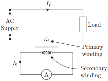
Circuit for measurement of current using a CT is given in Fig. 2.
Three types of core construction can be employed for CTs namely, core type, shell type and ring type.
The core type construction has an advantage that sufficient space is available for insulation purposes which makes it more suitable for high voltage work.
Shell type gives better protection for the windings.
Ring type is the most common of the core constructions for CT. It has very small leakage reactance as it has no joints in the core.
Transformer Burden
In CTs, the secondary has very small impedance referred to as burden, so the CT practically operates on short circuit conditions.
The burden for CT is the volt-ampere (VA) loading which is imposed on the secondary at rated current.
The burden can also be expressed as the ratio between secondary voltage and secondary current.
A metering CT has lower VA capacity than a protection CT. A metering CT has to be accurate over its complete measuring range. Such a CT’s magnetizing impedance at low current and hence low flux should be very high.
The magnetizing impedance is not constant for a CT’s operating range due to the non-linear characteristics of the B-H curve. It cannot give linear response during large fault currents.
For protection CT, linear response is expected for up to 20 times the rated current. It is also expected to give precise performance in the normal operating currents up to high fault level currents.
Voltage Transformer
Voltage or Potential transformer (PT) is a type of transformer used to measure high voltages; they basically function as step down transformers.
They have smaller number of secondary turns than turns in the primary.
Figure 4 shows a voltage transformer circuit.
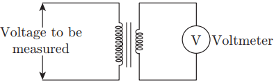
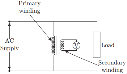
The voltage to be measured is connected across the primary circuit. The low voltage secondary circuit is connected to a voltmeter. The power rating of this type of transformer is usually lower. The circuit for measurement of voltage using a PT is given in Fig. 5.
Instrument Transformer Phasor Diagrams
CT Phasor Diagram
Figure 3 shows the phasor diagram for the current transformer.
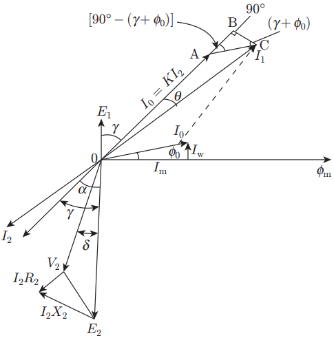
- Here, flux fm is taken as the reference.
- The no-load current I0 has two components, that is, the magnetising Im and the core loss component Iw.
- E1 and E2 are respectively the induced emf for the primary and secondary windings lagging behind the flux by 90°. The magnitudes of the emf are proportional to their number of turns in windings.
PT Phasor Diagram
Figure 6 shows the phasor diagram for a voltage transformer.
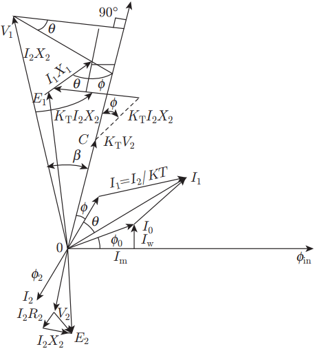
Starting with the flux reference, E2 is the induced emf in the secondary winding and V2 is the terminal voltage across the secondary. Then
V2 = E2 – I2R2cosɸ2 – I2X2sinɸ2
The primary induced emf E1 is in phase opposite to E2.
Difference between PT and CT
The main points of difference are listed as follows:
- The secondary of the CT is under short circuit as the primary circuit is energized, a PT can operate with its secondary under open circuit conditions without any damage to the transformer or to the operator.
- Under normal operating conditions, the line voltage of the PT is nearly steady. The flux density and the exciting current of a PT vary between small ranges. On the other hand, the primary current of a CT varies over wide ranges under normal operating conditions.
- The primary current of CT is independent of secondary winding conditions, while primary current in a PT depends on the secondary burden.
- For a PT, the primary is connected across full voltage. In case of CT, the primary is in series with a line and therefore a very small voltage exists across the terminals. The CT primary on the other hand carries full line current.
Errors in Instrument Transformers
There can be two types of errors in instrument transformers. These are listed as follows:
1. Ratio error: For CTs, the current transformation ratio should be constant. It should also be within the given limits. Practically, it can be seen sometimes this ratio may vary with power factor. This gives an error known as the ratio error.
The ratio between actual current transformation and the normal ratio is known as ratio correction factor (RCF). Mathematically,
RCF = Actual transformation ratio/Normal transformation ratio = k/kn
2. Phase angle error: This is the angle by which the secondary current differs in phase from the primary current when reversed. This error is due to no-load or exciting current in the transformer.
Error Minimization Methods
The magnetizing and core loss component of currents have to be kept at low values. The core material should have high value of permeability, large cross-section and shorter magnetic path in order to minimize these currents.
The materials from which the core can be constructed for this purpose are hot rolled silicon, cold rolled grain oriented silicon steel and nickel iron alloys.
Suitable turn ratio can be provided and number of secondary turns can be minimized by one or two turns.
Large current on the secondary should be reduced by putting a suitable valued shunt on either side. This process also reduces phase angle error in the instrument transformers.