Solar energy technologies produce electricity from the energy of the sun. Small solar energy systems can provide electricity for homes, businesses, and remote power needs. Larger solar energy systems can produce more electricity and feed the electric power system.
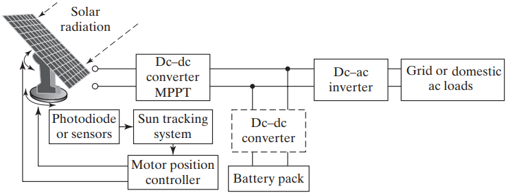
The block diagram of a solar energy system is shown in Figure 1. The system consists of tracking the sun, converting the solar energy into electrical energy, and then supplying to the grid or the ac loads. In some applications, it may be desirable to charge back-up or standby batteries. It often requires sun tracking devices and control for optimum energy delivery.
Solar Energy Systems
The generation of the solar power involves the following:
- Solar energy
- Photovoltaic (PV)
- Photovoltaic (PV) cells
- PV models
- PV modules and models
- Radiance and temperature effects
Solar Energy
Sun rays have high energy density in space, as much as 1.353 kW/m2 . But, the extra-terrestrial power density is lowered due to
- the absorption of some energy by various gases and water vapor in the earth’s atmosphere,
- the projection angle of the sun rays known as the zenith angle, and
- the various reflections and scatterings of sunrays.
The solar power density ρir on the earth, also called solar irradiance, can be determined by the following mathematical model developed by Atwater and Ball
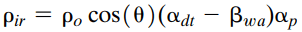
Where ρir = the solar power density on the earth’s surface (kW/m2 );
ρo = the extraterrestrial power density (usually 1.353 kW/m2 );
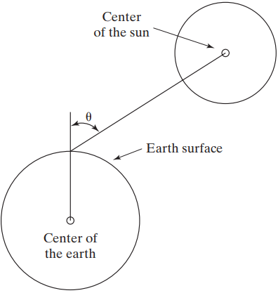
θ = the zenith angle (angle from the outward normal on the earth’s surface to the center of the sun), as shown in Figure 2;
αdt = the direct transmittance of gases except for water vapor, which is a fraction of radiant energy that is not absorbed by gases;
αp = the transmittance of aerosol;
βwa = the water vapor absorptions of radiation.
The term “aerosol” refers to atmospheric particles suspended in the earth’s atmosphere such as sulfate, nitrate, ammonium, chloride, and black carbon. The size of these particles normally ranges from 10–3 to 103 μm.
The solar power at the earth’s surface is only a fraction of the extraterrestrial solar power due to the losses of reflection, scattering, and absorption. The solar efficiency ηs, which is the ratio of the two solar power densities ρ and ρir, can be found from Eq. (1) as given by
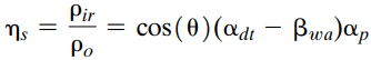
The solar efficiency varies from one place to another in the range between 5% and 70%. It is also a function of the season and the time of the day. The zenith angle as shown in Figure 2 has a major effect on the efficiency. The maximum efficiency occurs at noontime in the equator when θ = 0.
The regional solar resource maps and solar data can be found from the Solar and Wind Energy Resource Assessment (SWERA). SWERA provides high-quality information in suitable formats on renewable energy resources for countries and regions around the world, along with the tools needed to apply these data in ways that facilitate renewable energy policies and investments.
The peak solar power density during the day can reach values higher than 700 W/m2 . The solar power density with stable weather follows the bell-shaped curve, and it can be expressed by a normal distribution function as given by
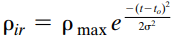
Where t is the hour of the day using the 24-h clock;
ρmax is the maximum solar power density of the day at to (noontime in the equator);
σ is the standard deviation of the normal distribution function.
The density ratio, as shown in Figure 3, is the percentage of the ratio ρir/ρmax.
When t = 12 ± σ, Eq. (3) gives ρir/ρmax = 0.607.
A large σ means wider areas under the distribution curve, that is, more solar energy is acquired during the day. In high latitudes, σ is smaller in the winter than in the summer. This is because daylight time is shorter during the winter as you move north.
Photovoltaic
Photovoltaic (PV) materials and devices convert sunlight into electrical energy, and PV cells are commonly known as solar cells. The PV cells are electricity-producing devices made of semiconductor materials.
Photovoltaics can literally be translated as light-electricity. Photovoltaic materials and devices convert light energy into electrical energy. The photoelectric or photovoltaic effect can cause certain materials to convert light energy into electrical energy at the atomic level.
PV systems are already an important part of our daily lives. Simple PV systems provide power for small consumer items such as calculators and wristwatches.
More complicated systems provide power for communications satellites, water pumps, lights, appliances, and machines in some homes and workplaces. Many road and traffic signs are also powered by PV. In many cases, PV power is the least expensive form of electricity for these tasks.
Photovoltaic Cells
PV cells are the building blocks of all PV systems because they are the devices that convert sunlight to electricity. PV cells come in many sizes and shapes, from smaller than a postage stamp to several inches across. They are often connected together to form PV modules that may be up to several feet long and a few feet wide.
Modules, in turn, can be combined and connected to form PV arrays of different sizes and power output. The modules of the array make up the major part of a PV system.
When light shines on a PV cell, it may be reflected, absorbed, or pass right through. But only the absorbed light generates electricity. The energy of the absorbed light is transferred to electrons in the atoms of the PV cell semiconductor material.
A special electrical property of the PV cell called a built-in-electric field provides the force, or voltage, needed to drive the current through an external load, such as a light bulb.
There are two types of PV cells: flat-plate and convex lenses.
The flat-plate PV is rectangular and flat. This is the most common type of PV array used in commercial applications. Flat-plate cells are often mounted at fixed angles that maximize the exposure to the sun throughout the year. In more flexible systems, the angle of the solar panel changes to track the optimal sun exposure during the day.
Convex lenses concentrating PV cells require less material for the same power output than the flat-plate cells; thus they are smaller in size. However, concentrating cells operate best when the sky is clear of clouds. On cloudy days, diffused light through the clouds can still produce electricity in flat-plate PV cells, whereas concentrating PV cells generate less power with diffused light.
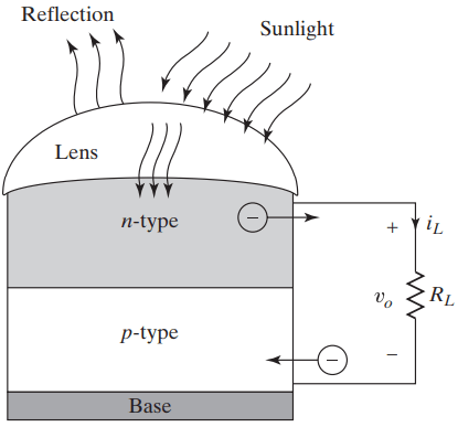
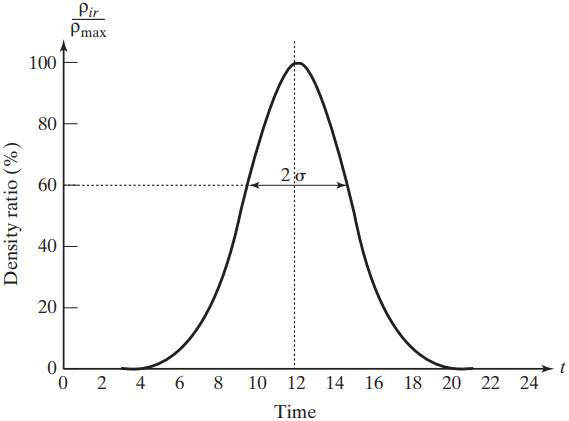
The principle of operation of PV cells is similar to that of the semiconductor diodes. The current flow through a diode is caused by applying an external voltage. But the current in a PV cell is caused by applying light, as shown in Figure 4a, and the parts of a PV cell are shown in Figure 4b.
The PV current can be related to the cell voltage by the Schockley Diode Equation
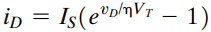
Where iD = current through the diode, A;
vD = diode voltage with anode positive with respect to cathode, V;
IS = leakage (or reverse saturation) current, typically in the range 10-6 to 10-15A;
η = empirical constant known as emission coefficient, or ideality factor, whose value varies from 1 to 2.
PV Models
As content of this section involves too much equations which is presentable only in a PDF format. So to read that content please refer to the PDF file.
Photovoltaic Systems
An individual PV cell is usually small, as shown in Figure 5a, typically producing about 1 or 2 watts of power which may be enough to run a low-power calculator. Since the PV cell is essentially a diode, the forward-biased voltage of a diode is typically 0.7 V.
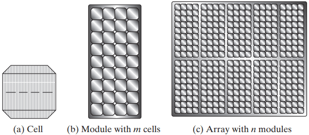
The PV cells are connected together in parallel and series arrangements to increase the power rating. To boost the power output of PV cells, they are connected together to form larger units called modules, as shown in Figure 5b.
If V is the voltage of a cell and m number of cells are connected in series, the voltage of a module is Vmod = mV. Modules, in turn, can be connected in parallel to form even larger units called arrays, which can be interconnected to produce more power, as shown in Figure 5c.
If I is the current capability of a cell and n numbers of modules are connected in parallel, the current capability of an array is Iar = nI. Therefore, the output power of a cell array becomes Par = mnVI. That is, the array power becomes mn times of a single cell power Pc. For example, if Pc = 2W, m = 4, and n = 20, Par = 2 * 4 * 20 = 160W.
In this way, PV systems can be built to meet almost any electric power need, small or large. Several of these arrays form a PV system. More sophisticated PV arrays are mounted on tracking devices that follow the sun throughout the day. The tracking devices tilt the PV arrays to maximize the exposure of the cells to the sun rays.
Related Posts
- Solar Energy Systems
- Solar Cell | Photovoltaic Cell
- Solar Concentrator PV Systems
- 3D Solar Cells
- 3D Solar Cell Systems
- Electrical Specifications of PV Modules
- Standard Test Conditions for PV Modules
- PV Arry Charge Controllers
- Sizing a Grid-Direct PV System
- Sizing a Battery-Based PV System
- Site Survey for PV Installation
- Understanding Solar Radiation for PV Installlation
- Concentrating Solar Collectors
- Solar Energy Systems
- Solar Panel Working Principle