The oscilator, which typically varies in frequency from Hz to a few MHz, is an electronic device used to convert DC energy into AC energy with a high frequency. An external signal source, such as an amplifier, is not required for an oscillator. Oscillators typically come in two varieties: sinusoidal and non-sinusoidal. While non-sinusoidal oscillators produce complicated waveforms like triangular, square-wave, and sawtooth oscillations, sinusoidal oscillators produce sine waves developed at steady frequency & amplitude.
Therefore, a general overview of a transistor acting as an oscillator or transistor oscillator – working with applications – is covered in this article. If you want to get more information about the oscillator or transistor, you can look at the Electronic Part to see the products or specifications about them.
Transistor Oscillator Circuit Diagram
The transistor oscillator’s circuit diagram is displayed below. This circuit makes it easy to demonstrate how to use a transistor as an oscillator. The three components of this circuit are organized as follows.
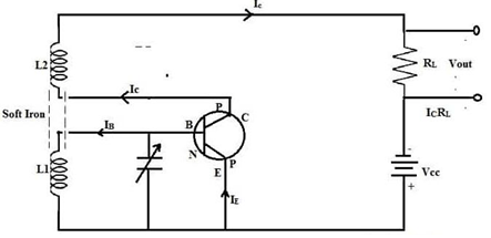
Tank Circuit
The transistor changes the oscillations the tank circuit produces and amplifies the output on the collector side.
Amplifier Circuit
The base-emitter circuit’s minuscule sinusoidal oscillations are amplified by this circuit, and the amplified output is created.
Feedback Circuit
Because an amplifier needs some energy to magnify at the tank circuit, the feedback circuit is a crucial part of this circuit. As a result, the base circuit receives energy from the collector circuit via the Mutual induction phenomena. The energy is transferred back from the output to the input using this circuit.
Oscillation Conditions
The transistor oscillator circuit must follow the following:
- The phase shift of the loop should be 0 & 360 degrees.
- The loop gain must be >1.
- If a sinusoidal signal is a preferred output, then a loop gain > 1 will quickly cause the o/p to saturate at both waveform peaks & generating unacceptable distortion.
- If the gain of the amplifier is >100, then it will cause the oscillator to limit both the waveform peaks. To meet the above conditions, the oscillator circuit should include some type of amplifier, as well as a part of its output, which should be fed back to the input. To conquer the losses within the input circuit, we utilize the feedback circuit. If the amplifier’s gain is <1, then the oscillator circuit will not oscillate and if it is > 1, then the circuit will oscillate and generate distorted signals.
Types of Transistor Oscillator
Although there are many distinct types of oscillators, they all serve the same purpose. Thus, they produce undamped output that is continuous. However, they adjust their method of supplying power to the oscillatory or tank circuit to accommodate the ranges of frequencies and losses they are used in.
High-frequency outputs are frequently produced by transistor oscillators using LC circuits as their oscillatory or tank circuits. Below is a discussion of the various types of transistor oscillators.
Hartley Oscillator
One type of electronic oscillator used to determine oscillation frequency through a tuned circuit is the Hartley oscillator. The primary distinguishing characteristic of this oscillator is that the tuned circuit consists of a single capacitor linked in parallel through two inductors connected in series, and that the feedback signal needed for oscillation is derived from the center connection of the two inductors. The Hartley oscillator is suitable for oscillations up to 30MHz in the RF band.
Crystal Oscillator
“The transistor crystal oscillator is useful in a variety of electrical and radio applications. These oscillators are essential for supplying a low-cost CLK signal for use in logic or digital circuits. Other uses for this oscillator include supplying a steady and accurate RF signal source. Therefore, radio amateurs (also known as radio hams) typically use these oscillators in radio transmitter circuits, where they are most useful.
Colpitt’s Oscillator
The only difference between the Colpitts oscillator and the Hartley oscillator is that within the tank circuit, the inductors and capacitors are swapped out for one another. The key advantage of this type of oscillator is that the oscillator’s frequency stability is increased by having less mutual and self-inductance in the tank circuit. Based on sinusoidal inputs, this oscillator generates very high frequencies. These oscillators can endure both low and high temperatures and have high-frequency stability.
Wien Bridge Oscillator
Due to its useful characteristics, the Wien bridge oscillator is a widely utilized audio frequency oscillator. This kind of oscillator is unaffected by variations and by the circuit’s ambient temperature. This type of oscillator’s key advantage is that it can alter the frequency range from 10Hz to 1MHz. Therefore, this oscillator circuit provides good frequency stability.
Phase Shift Oscillator
One type of oscillator is an RC phase shift oscillator, where the required phase shift toward the feedback signal is provided by a straightforward RC network. This oscillator, like Hartley and Colpitts’ oscillator, uses an LC network to deliver the necessary positive feedback. This oscillator produces pure sine waves over a wide range of loads and exhibits exceptional frequency stability.
Applications
The applications of a transistor as an oscillator include the following.
- If oscillatory & feedback circuits are appropriately linked to a transistor oscillator, it can be utilized to produce consistent undamped oscillations at any desired frequency.
- The Wien bridge oscillator is extensively used for AC bridge excitation as well as for testing power amplifier distortion and audio quality.
- Radio receivers use Hartley oscillators.
- High frequency sinusoidal output signals are produced using Colpitt’s oscillator.
- These are widely used in telecommunications, instrumentation, computers, modems, digital systems, marine, phase-locked loop systems, and sensors.