Starting Methods of Induction Motors
Our everyday domestic experience is likely to lead us to believe that there is nothing more to starting a motor than closing a switch, and indeed for most low-power machines (say up to a few kW ) – of whatever type – that is indeed the case. By simply connecting the motor to the supply we set in train a sequence of events which sees the motor draw power from the supply while it accelerates to its target speed.
When it has absorbed and converted sufficient energy from electrical to kinetic form, the speed stabilises and the power drawn falls to a low level until the motor is required to do useful mechanical work.
In these low-power applications acceleration to full speed may take less than a second, and we are seldom aware of the fact that the current drawn during the acceleration phase is often higher than the continuous rated current.
For motors over a few kW, however, it is necessary to assess the effect on the supply system before deciding whether or not the motor can be started simply by switching directly onto the supply. If supply systems were ideal (i.e. the supply voltage remained unaffected regardless of how much current was drawn) there would be no problem starting any induction motor, no matter how large.
The problem is that the heavy current drawn while the motor is running up to speed may cause a large drop in the supply system voltage, annoying other customers on the same supply and perhaps taking it outside statutory limits. It is worthwhile reminding ourselves about the influence of supply impedance at this point, as this is at the root of the matter, so we begin by noting that any supply system, no matter how complicated, can be modelled by means of the delightfully simple Thevenin equivalent circuit shown in Figure 1. (We here assume a balanced 3-phase operation, so a 1-phase equivalent circuit will suffice.)
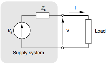
The supply is represented by an ideal voltage source (Vs) in series with the supply impedance Zs. When no load is connected to the supply, and the current is zero, the terminal voltage is Vs; but as soon as a load is connected the load current (I) flowing through the source impedance results in a volt drop, and the output voltage falls from Vs to V, where
V = Vs – IZs
For most industrial supplies the source impedance is predominantly inductive, so that Zs is simply an inductive reactance, Xs.
Typical phasor diagrams relating to a supply with a purely inductive reactance are shown in Figure 2: in (a) the load is also taken to be purely reactive, while the load current in (b) has the same magnitude as in (a) but the load is resistive. The output (terminal) voltage in each case is represented by the phasor labelled V.
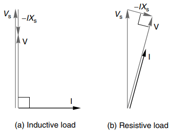
For the inductive load (a) the current lags the terminal voltage by 90o while for the resistive load (b) the current is in phase with the terminal voltage. In both cases the volt drop across the supply reactance (IXs) leads the current by 90o.
The first point to note is that, for a given magnitude of load current, the volt drop is in phase with Vs when the load is inductive, whereas with a resistive load the volt drop is almost at 90o to Vs.
This results in a much greater fall in the magnitude of the output voltage when the load is inductive than when it is resistive. The second, obvious, point is that the larger the current, the more the drop in voltage.
Unfortunately, when we try to start a large cage induction motor we face a double-whammy because not only is the starting current typically five or six times rated current, but it is also at a low-power factor, i.e. the motor looks predominantly inductive when the slip is high.
In contrast, when the machine is up to speed and fully loaded, its current is perhaps only one fifth of its starting current and it presents a predominantly resistive appearance as seen by the supply. Under these conditions the supply voltage is hardly any different from at no-load.
Since the drop in voltage is attributable to the supply impedance, if we want to be able to draw a large starting current without upsetting other consumers it would be clearly best for the supply impedance to be as low as possible, and preferably zero.
But from the supply authority viewpoint a very low supply impedance brings the problem of how to scope in the event of an accidental short-circuit across the terminals. The short-circuit current is inversely proportional to the supply impedance, and tends to infinity as Zs approaches zero.
The cost of providing the switch-gear to clear such a large fault current would be prohibitive, so a compromise always has to be reached, with values of supply impedances being set by the supply authority to suit the anticipated demands. Systems with a low internal impedance are known as ‘stiff’ supplies, because the voltage is almost constant regardless of the current drawn.
(An alternative way of specifying the nature of the supply is to consider the fault current that would flow if the terminals were short-circuited: a system with a low impedance would have a high fault current or ‘fault level’.) Starting on a stiff supply requires no special arrangements and the three motor leads are simply switched directly onto the mains.
Direct On Line Starting
This is known as ‘direct-on-line’ (DOL) or ‘direct-to-line’ (DTL) starting. The switching will usually be done by means of a relay or contactor, incorporating fuses and other overload protection devices, and operated manually by local or remote pushbuttons, or interfaced to permit operation from a programmable controller or computer.
In contrast, if the supply impedance is high (i.e. a low-fault level) an appreciable volt drop will occur every time the motor is started, causing lights to dim and interfering with other apparatus on the same supply. With this ‘weak’ supply, some form of starter is called for to limit the current at starting and during the run-up phase, thereby reducing the magnitude of the volt drop imposed on the supply system. As the motor picks up speed, the current falls, so the starter is removed as the motor approaches full speed.
Naturally enough the price to be paid for the reduction in current is a lower starting torque, and a longer run-up time. Whether or not a starter is required depends on the size of the motor in relation to the capacity or fault level of the supply, the prevailing regulations imposed by the supply authority, and the nature of the load.
The references above to ‘low’ and ‘high’ supply impedances must therefore be interpreted in relation to the impedance of the motor when it is stationary. A large (and therefore low impedance) motor could well be started quite happily DOL in a major industrial plant, where the supply is ‘stiff’, i.e. the supply impedance is very much less than the motor impedance.
But the same motor would need a starter when used in a rural setting remote from the main power system, and fed by a relatively high impedance or ‘weak’ supply. Needless to say, the stricter the rules governing permissible volt drop, the more likely it is that a starter will be needed.
Motors which start without significant load torque or inertia can accelerate very quickly, so the high starting current is only drawn for a short period. A 10 kW motor would be up to speed in a second or so, and the volt drop may therefore be judged as acceptable. Clutches are sometimes fitted to permit ‘off-load’ starting, the load being applied after the motor has reached full speed.
Conversely, if the load torque and/or inertia are high, the run-up may take many seconds, in which case a starter may prove essential. No strict rules can be laid down, but obviously the bigger the motor, the more likely it is to require a starter.
Starting Methods of Induction Motors
Star/Delta (Wye/Mesh) Starter
This is the simplest and most widely used method of starting. It provides for the windings of the motor to be connected in star (wye) to begin with, thereby reducing the voltage applied to each phase to 58% (1/√3) of its DOL value. Then, when the motor speed approaches its running value, the windings are switched to delta (mesh) connection.
The main advantage of the method is its simplicity, while its main drawbacks are that the starting torque is reduced, and the sudden transition from star to delta gives rise to a second shock – albeit of lesser severity – to the supply system and to the load.
For star/delta switching to be possible both ends of each phase of the motor windings must be brought out to the terminal box. This requirement is met in the majority of motors, except small ones which are usually permanently connected in delta.
With a star/delta starter the current drawn from the supply is approximately one third of that drawn in a DOL start, which is very welcome, but at the same time the starting torque is also reduced to one third of its DOL value. Naturally we need to ensure that the reduced torque will be sufficient to accelerate the load, and bring it up to a speed at which it can be switched to delta without an excessive jump in the current. Various methods are used to detect when to switch from star to delta.
In manual starters, the changeover is determined by the operator watching the ammeter until the current has dropped to a low level, or listening to the sound of the motor until the speed becomes steady. Automatic versions are similar in that they detect either falling current or speed rising to a threshold level, or else they operate after a preset time.
Autotransformer Starter
A 3-phase autotransformer is usually used where star/delta starting provides insufficient starting torque. Each phase of an autotransformer consists of a single winding on a laminated core. The mains supply is connected across the ends of the coils, and one or more tapping points (or a sliding contact) provide a reduced voltage output, as shown in Figure 3.
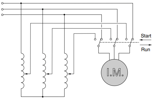
The motor is first connected to the reduced voltage output, and when the current has fallen to the running value, the motor leads are switched over to the full voltage. If the reduced voltage is chosen so that a fraction α of the line voltage is used to start the motor, the starting torque is reduced to approximately α2 times its DOL value, and the current drawn from the mains is also reduced to α2 times its direct value.
As with the star/delta starter, the torque per ampere of supply current is the same as for a direct start. The switchover from the starting tap to the full voltage inevitably results in mechanical and electrical shocks to the motor.
In large motors the transient over-voltages caused by switching can be enough to damage the insulation, and where this is likely to pose a problem a modified procedure known as the Korndorfer method is used. A smoother changeover is achieved by leaving part of the winding of the autotransformer in series with the motor winding all the time.
Resistance or Reactance Starter
By inserting three resistors or inductors of appropriate value in series with the motor, the starting current can be reduced by any desired extent, but only at the expense of a disproportionate reduction in starting torque.
For example, if the current is reduced to half its DOL value, the motor voltage will be halved, so the torque (which is proportional to the square of the voltage) will be reduced to only 25% of its DOL value.
This approach is thus less attractive in terms of torque per ampere of supply current than the star/delta method. One attractive feature, however, is that as the motor speed increases and its effective impedance rises, the volt drop across the extra impedance reduces, so the motor voltage rises progressively with the speed, thereby giving more torque. When the motor is up to speed, the added impedance is shorted-out by means of a contactor.
Variable-resistance starters (manually or motor operated) are sometimes used with small motors where a smooth jerk free start is required, for example in film or textile lines.
Solid State Soft Starting
This method is now the most widely used. It provides a smooth build-up of current and torque, the maximum current and acceleration time are easily adjusted, and it is particularly valuable where the load must not be subjected to sudden jerks. The only real drawback over conventional starters is that the mains currents during run-up are not sinusoidal, which can lead to interference with other equipment on the same supply.
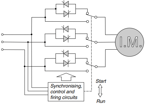
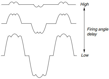
The most widely used arrangement comprises three pairs of back-to-back thyristors connected in series with three supply lines, as shown in Figure 4(a). Each thyristor is fired once per half-cycle, the firing being synchronised with the mains and the firing angle being variable so that each pair conducts for a varying proportion of a cycle.
Typical current waveforms are shown in Figure 4(b): they are clearly not sinusoidal but the motor will tolerate them quite happily. A wide variety of control philosophies can be found, with the degree of complexity and sophistication being reflected in the price.
The cheapest open-loop systems simply alter the firing angle linearly with time, so that the voltage applied to the motor increases as it accelerates. The ‘ramp-time’ can be set by trial and error to give an acceptable start, i.e. one in which the maximum allowable current from the supply is not exceeded at any stage. This approach is reasonably satisfactory when the load remains the same, but requires resetting each time the load changes.
Loads with high static friction are a problem because nothing happens for the first part of the ramp, during which time the motor torque is insufficient to move the load. When the load finally moves, its acceleration is often too rapid. The more advanced open-loop versions allow the level of current at the start of the ramp to be chosen, and this is helpful with ‘sticky’ loads.
More sophisticated systems – usually with on-board digital controllers – provide for tighter control over the acceleration profile by incorporating closed-loop current feedback. After an initial ramping up to the start level (over the first few cycles), the current is held constant at the desired level throughout the accelerating period, the firing angle of the thyristors being continually adjusted to compensate for the changing effective impedance of the motor. By keeping the current at the maximum value, which the supply can tolerate the run-up time, is minimised.
Alternatively, if a slow run-up is desirable, a lower accelerating current can be selected. As with the open-loop systems the velocity–time profile is not necessarily ideal, since with constant current the motor torque exhibits a very sharp rise as the pullout slip is reached, resulting in a sudden surge in speed.
Prospective users need to be wary of some of the promotional literature, where naturally enough the virtues are highlighted while the shortcomings are played down. Claims are sometimes made that massive reductions in starting current can be achieved without corresponding reductions in starting torque.
This is nonsense: the current can certainly be limited, but as far as torque per line amp is concerned soft-start systems are no better than series reactor systems, and not as good as the autotransformer and star/delta methods.
Starting Using Variable Frequency Inverter
One of the advantages of inverter-fed motor operation is that starting is not a problem because it is usually possible to obtain at least rated torque at zero speed without drawing an excessive current from the mains supply.
None of the other starting methods we have looked at have this ability, so in some applications it may be that the comparatively high cost of the inverter is justified solely on the grounds of its starting and run-up potential.