Transient Performance of Stepping Motors
Step Response
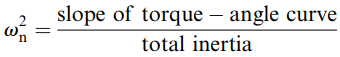
It was pointed out earlier that the single-step response is similar to that of a damped second-order system. We can easily estimate the natural frequency ωn in rad/s from the equation
Knowing ωn, we can judge what the oscillatory part of the response will look like, by assuming the system is undamped. To refine the estimate, and to obtain the settling time, however, we need to estimate the damping ratio, which is much more difficult to determine as it depends on the type of drive circuit and mode of operation as well as on the mechanical friction.
In VR motors the damping ratio can be as low as 0.1, but in hybrid types it is typically 0.3–0.4. These values are too low for many applications where rapid settling is called for.
Two remedies are available, the simplest being to fit a mechanical damper of the type mentioned above.
Alternatively, a special sequence of timed command pulses can be used to brake the rotor so that it reaches its new step position with zero velocity and does not overshoot. This procedure is variously referred to as ‘electronic damping’, ‘electronic braking’ or ‘back phasing’.
It involves re-energising the previous phase for a precise period before the rotor has reached the next step position, in order to exert just the right degree of braking. It can only be used successfully when the load torque and inertia are predictable and not subject to change.
Because it is an open-loop scheme it is extremely sensitive to apparently minor changes such as day-to-day variation in friction, which can make it unworkable in many instances.
Starting from Rest
The rate at which the motor can be started from rest without losing steps is known as the ‘starting’ or ‘pull-in’ rate.
The starting rate for a given motor depends on the type of drive, and the parameters of the load. This is entirely as expected since the starting rate is a measure of the motor’s ability to accelerate its rotor and load and pull into synchronism with the field. The starting rate thus reduces if either the load torque, or the load inertia are increased.
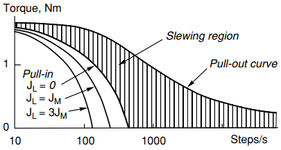
Typical pull-in torque–speed curves, for various inertias, are shown in Figure 1. The pull-out torque–speed curve is also shown, and it can be seen that for a given load torque, the maximum steady (slewing) speed at which the motor can run is much higher than the corresponding starting rate.
Note that only one pull-out torque is usually shown, and is taken to apply for all inertia values. This is because the inertia is not significant when the speed is constant.
It will normally be necessary to consult the manufacturer’s data to obtain the pull-in rate, which will apply only to a particular drive. However, a rough assessment is easily made: we simply assume that the motor is producing its pull-out torque, and calculate the acceleration that this would produce, making due allowance for the load torque and inertia.
If, with the acceleration as calculated, the motor is able to reach the steady speed in one step or less, it will be able to pull-in; if not, a lower pull-in rate is indicated.
Optimum Acceleration and Closed Loop Control
There are some applications where the maximum possible accelerations and decelerations are demanded, in order to minimise point-to-point times. If the load parameters are stable and well defined, an open-loop approach is feasible, and this is discussed first. Where the load is unpredictable, however, a closed-loop strategy is essential, and this is dealt with later.
To achieve maximum possible acceleration calls for every step command pulse to be delivered at precisely optimised intervals during the acceleration period. For maximum torque, each phase must be on whenever it can produce positive torque, and off when its torque would be negative.
Since the torque depends on the rotor position, the optimum switching times have to be calculated from a full dynamic analysis. This can usually be accomplished by making use of the static torque–angle curves (provided appropriate allowance is made for the rise and fall times of the stator currents), together with the torque–speed characteristic and inertia of the load.
A series of computations is required to predict the rotor angle–time relationship, from which the switchover points from one phase to the other are deduced. The train of accelerating pulses is then pre-programmed into the controller, for subsequent feeding to the drive in an open-loop fashion.
It is obvious that this approach is only practicable if the load parameters do not vary, since any change will invalidate the computed optimum stepping intervals.
When the load is unpredictable, a much more satisfactory arrangement is obtained by employing a closed-loop scheme, using position feedback from a shaft-mounted encoder.
The feedback signals indicate the instantaneous position of the rotor, and are used to ensure that the phase-windings are switched at precisely the right rotor position for maximising the developed torque.
Motion is initiated by a single command pulse, and subsequent step command pulses are effectively self-generated by the encoder. The motor continues to accelerate until its load torque equals the load torque, and then runs at this (maximum) speed until the deceleration sequence is initiated. During all this time, the step counter continues to record the number of steps taken.
Closed-loop operation ensures that the optimum acceleration is achieved, but at the expense of more complex control circuitry, and the need to fit a shaft encoder. Relatively cheap encoders are, however, now available for direct fitting to some ranges of motors, and single chip microcontrollers are available which provide all the necessary facilities for closed-loop control.
An appealing approach aimed at eliminating an encoder is to detect the position of the rotor by online analysis of the signals (principally the rates of change of currents) in the motor windings themselves: in other words, to use the motor as its own encoder.
A variety of approaches have been tried, including the addition of high-frequency alternating voltages superimposed on the excited phase, so that as the rotor moves the variation of inductance results in a modulation of the alternating current component. Some success has been achieved with particular motors, but the approach has not yet achieved widespread commercial exploitation.
To return finally to encoders, we should note that they are also used in open-loop schemes when an absolute check on the number of steps taken is required. In this context the encoder simply provides a tally of the total steps taken, and normally plays no part in the generation of the step pulses.
At some stage, however, the actual number of steps taken will be compared with the number of step command pulses issued by the controller. When a disparity is detected, indicating a loss (or gain of steps), the appropriate additional forward or backward pulses can be added.