Astable, Monostable & Bistable Multivibrator
Multivibrators, like the familiar sinusoidal oscillators, are circuits with regenerative feedback, with the difference that they produce pulsed output. There are three basic types of multivibrator, namely
- the bistable multivibrator,
- the monostable multivibrator and
- the astable multivibrator.
Bistable Multivibrator
A bistable multivibrator circuit is one in which both LOW and HIGH output states are stable. Irrespective of the logic status of the output, LOW or HIGH, it stays in that state unless a change is induced by applying an appropriate trigger pulse. As we will see in the subsequent pages, the operation of a bistable multivibrator is identical to that of a flip-flop.
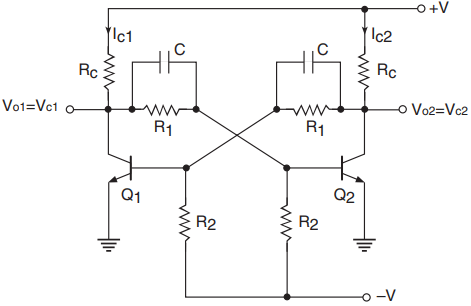
Figure 1 shows the basic bistable multivibrator circuit. This is the fixed-bias type of bistable multivibrator. Other configurations are the self-bias type and the emitter-coupled type. However, the operational principle of all types is the same. The multivibrator circuit of Fig. 1 functions as follows.
In the circuit arrangement of Fig. 1 it can be proved that both transistors Q1 and Q2 cannot be simultaneously ON or OFF. If Q1 is ON, the regenerative feedback ensures that Q2 is OFF, and when Q1 is OFF, the feedback drives transistor Q2 to the ON state.
In order to vindicate this statement, let us assume that both Q1 and Q2 are conducting simultaneously. Owing to slight circuit imbalance, which is always there, the collector current in one transistor will always be greater than that in the other.
Let us assume that Ic2 > Ic1 Lesser Ic1 means a higher Vc1. Since Vc1 is coupled to the Q2 base, a rise in Vc1 leads to an increase in the Q2 base voltage. Increase in the Q2 base voltage results in an increase in Ic2 and an associated reduction in Vc2 Reduction in Vc2 leads to a reduction in Q1 base voltage and an associated fall in Ic1, with the result that Vc1 increases further.
Thus, a slight circuit imbalance has initiated a regenerative action that culminates in transistor Q1 going to cut-off and transistor Q2 getting driven to saturation.
To sum up, whenever there is a tendency of one of the transistors to conduct more than the other, it will end up with that transistor going to saturation and driving the other transistor to cut-off.
Now, if we take the output from the Q1 collector, it will be LOW (= VCE1 sat.) if Q1 was initially in saturation. If we apply a negative-going trigger to the Q1 base to cause a decrease in its collector current, a regenerative action would set in that would drive Q2 to saturation and Q1 to cut-off. As a result, the output goes to a HIGH (= +VCC) state. The output will stay HIGH until we apply another appropriate trigger to initiate a transition.
Thus, both of the output states, when the output is LOW and also when the output is HIGH, are stable and undergo a change only when a transition is induced by means of an appropriate trigger pulse. That is why it is called a bistable multivibrator.
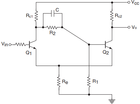
Schmitt Trigger: A Schmitt trigger circuit is a slight variation of the bistable multivibrator circuit of Fig. 1. Figure 2 shows the basic Schmitt trigger circuit. If we compare the bistable multivibrator circuit of Fig. 1 with the Schmitt trigger circuit of Fig. 2, we find that coupling from Q2 collector to Q1 base in the case of a bistable circuit is absent in the case of a Schmitt trigger circuit. Instead, the resistance Re provides the coupling. The circuit functions as follows.
When Vin is zero, transistor Q1 is in cut-off. Coupling from Q1 collector to Q2 base drives transistor Q2 to saturation, with the result that Vo is LOW. If we assume that VCE2 (sat.) is zero, then the voltage across Re is given by the equation Voltage across
Re = [VCCRe/(Re +Rc2)]……..(1)
This is also the emitter voltage of transistor Q1. In order to make transistor Q1 conduct, Vin must be at least 0.7 V more than the voltage across Re. That is,
Vinmin = [VCCRe/(Re +Rc2)] + 0.7 ……..(2)
When Vin exceeds this voltage, Q1 starts conducting. The regenerative action again drives Q2 to cut-off. The output goes to the HIGH state. Voltage across Re changes to a new value given by the equation Voltage across
Re = [VCCRe/(Re +Rc1)] ……(3)
Vin = [VCCRe/(Re +Rc1)] + 0.7……. (4)
Transistor Q1 will continue to conduct as long as Vin is equal to or greater than the value given by Equation (4).
If Vin falls below this value, Q1 tends to come out of saturation and conduct less heavily. The regenerative action does the rest, with the process culminating in Q1 going to cut-off and Q2 to saturation. Thus, the state of output (HIGH or LOW) depends upon the input voltage level.
The HIGH and LOW states of the output correspond to two distinct input levels given by Equations (2) and (4) and therefore the values of Rc1,Rc2,Re and VCC.The Schmitt trigger circuit of Fig. 2 therefore exhibits hysteresis.
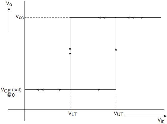
Figure 3 shows the transfer characteristics of the Schmitt trigger circuit. The lower trip point VLT and the upper trip point VUT of these characteristics are respectively given by the equations
VLT = [VCCRe/(Re +Rc1)] + 0.7……. (5)
VUT = [VCCRe/(Re +Rc2)] + 0.7……. (6)
Monostable Multivibrator
A monostable multivibrator, also known as a monoshot, is one in which one of the states is stable and the other is quasi-stable. The circuit is initially in the stable state. It goes to the quasi-stable state when appropriately triggered. It stays in the quasi-stable state for a certain time period, after which it comes back to the stable state.
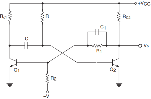
Figure 4 shows the basic monostable multivibrator circuit. The circuit functions as follows.
Initially, transistor Q2 is in saturation as it gets its base bias from +VCC through R Coupling from Q2 collector to Q1 base ensures that Q1 is in cut-off. Now, if an appropriate trigger pulse induces a transition in Q2 from saturation to cut-off, the output goes to the HIGH state.
This HIGH output when coupled to the Q1 base turns Q1 ON. Since there is no direct coupling from Q1 collector to Q2 base, which is necessary for a regenerative process to set in, Q1 is not necessarily in saturation. However, it conducts some current.
The Q1 collector voltage falls by Ic1Rc1 and the Q2 base voltage falls by the same amount, as the voltage across a capacitor (C in this case) cannot change instantaneously.
To sum up, the moment we applied the trigger, Q2 went to cut-off and Q1 started conducting. But now there is a path for capacitor C to charge from VCC through R and the conducting transistor. The polarity of voltage across C is such that the Q2 base potential rises.
The moment the Q2 base voltage exceeds the cut-in voltage, it turns Q2 ON, which, owing to coupling through R1, turns Q1 OFF. And we are back to the original state, the stable state.
Whenever we trigger the circuit into the other state, it does not stay there permanently and returns back after a time period that depends upon R and C. The greater the time constant RC, the longer is the time for which it stays in the other state, called the quasi-stable state.
Retriggerable Monostable Multivibrator: In a conventional monostable multivibrator, once the output is triggered to the quasi-stable state by applying a suitable trigger pulse, the circuit does not respond to subsequent trigger pulses as long as the output is in quasi-stable state. After the output returns to its original state, it is ready to respond to the next trigger pulse.
There is another class of monostable multivibrators, called retriggerable monostable multivibrators. These respond to trigger pulses even when the output is in the quasi-stable state.
In this class of monostable multivibrators, if n trigger pulses with a time period of Tt are applied to the circuit, the output pulse width, that is, the time period of the quasi-stable state, equals (n−1)Tt +T, where T is the output pulse width for the single trigger pulse and Tt < T.
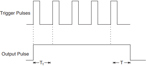
Figure 5 shows the output pulse width in the case of a retriggerable monostable multivibrator for repetitive trigger pulses.
Astable Multivibrator
In the case of an astable multivibrator, neither of the two states is stable. Both output states are quasistable. The output switches from one state to the other and the circuit functions like a free-running square-wave oscillator.
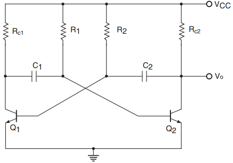
Figure 6 shows the basic astable multivibrator circuit. It can be proved that, in this type of circuit, neither of the output states is stable. Both states, LOW as well as HIGH, are quasi-stable. The time periods for which the output remains LOW and HIGH depends upon R2C2 and R1C1 time constants respectively. For R1C1 = R2C2, the output is a symmetrical square waveform. The circuit functions as follows.
Let us assume that transistor Q2 is initially conducting, that is, the output is LOW. Capacitor C2 in this case charges through R2 and the conducting transistor from VCC, and, the moment the Q1 base potential exceeds its cut-in voltage, it is turned ON.
A fall in Q1 collector potential manifests itself at the Q2 base as voltage across a capacitor cannot change instantaneously. The output goes to the HIGH state as Q2 is driven to cut-off. However, C1 has now started charging through R1 and the conducting transistor Q1 from VCC. The moment the Q2 base potential exceeds the cut-in voltage, it is again turned ON, with the result that the output goes to the LOW state.
This process continues and, owing to both the couplings (Q1 collector to Q2 base and Q2 collector to Q1 base) being capacitive, neither of the states is stable. The circuit produces a square-wave output.
Related Posts
- Logic Gates
- Significance & Types of Logic Family
- Characteristics Parameters of Logic Families
- TTL Logic Family
- ECL Logic Family
- CMOS Logic Family
- Interfacing of Logic Families
- Microcontroller Architecture
- Components of Microcontroller
- Interfacing Devices with Microcontroller
- IC Based Multivibrator Circuits
- Astable, Monostable & Bistable Multivibrator
- Logic Analyser
- Types of Oscilloscope
- Frequency Synthesizers
- Frequency Counter