Applications of Insulating Materials
Insulating fluids (gases and liquids) provide insulation between phases and between phase and grounded parts of electrical equipment. These also carry out heat from the windings of the electrical equipment. However, solid insulating materials are used only to provide insulation.
While describing the dielectric and other properties of various insulating materials, their application for various electrical apparatus has also been mentioned in the previous paragraphs. However, a reverse process i.e., what insulating materials are used for a particular apparatus depending upon its ratings and environmental condition where the apparatus is required to operate, is also desirable, and a brief review is given here.
Applications of Insulating Materials in Power Transformers
For small ratings, the coils are made of super-enameled copper wire. For layer to layer, coil to coil, and coil to the ground (iron core) craft paper is used. However, for large-sized transformers paper or glass tape is rapped on the rectangular conductors whereas, for coil-to-coil or coil-to-ground, insulation is provided using thick radial spacers made of press board or glass fiber.
In oil-filled transformers, the transformer oil is the main insulation. However, various layers of low-voltage and high-voltage winding oil-impregnated press boards are placed.
SF6 gas-insulated power transformers make use of sheet aluminum conductors for windings and turn-to-turn insulation is provided by a polymer film. The transformer has annular cooling ducts through which SF6 gas circulates for cooling the winding. SF6 gas provides insulation to all major gaps in the transformer. This transformer is used where oil-filled transform is not suitable e.g., in cinema halls, high-rise buildings, and in some special circumstances.
The end turns of a large power transformer are provided with extra insulation to avoid damage to the coil when lighting or switching surges of high frequency are incident on the transformer winding.
The terminal bushings of large-size power transformers are made of condenser-type bushing. The terminal itself consists of a brass rod or tube that is wound with alternate layers of treated paper and tin foil, so proportioned, as to length, that the series of condensers formed by the tin foil cylinders and the intervening insulation have equal capacitances, thereby the dielectric stress is distributed uniformly.
Circuit Breakers
The basic construction of any circuit breaker requires the separation of contacts in an insulating fluid which serves two functions here:
- It extinguishes the arc drawn between the contacts when the CB, opens.
- It provides adequate insulation between the contacts and from each contact to the earth.
Many insulating fluids are used for arc extinction and the fluid chosen depends upon the rating and type of C.B. The insulating fluids commonly used for circuit breakers are:-
- Air at atmospheric pressure: Air break circuit breaker up to 11 kV.
- Compressed air: Air blast circuit breaker between 220 kV and 400 kV
- Mineral oil which produces hydrogen for arc extinction (transformer oil) (a) Plain break oil C.B. 11 kV – 66 kV (b) Controlled break oil C.B. or bulk oil C.B. between 66 kV – 220 kV (c) Minimum oil C.B. between 66 kV and 132 kV.
- Ultra high vacuum C.B. up to 33 kV.
- SF6 circuit breakers above 220 kV.
The controlled break and minimum oil circuit breakers enclose the breaker contacts in an arcing chamber made of insulating materials such as glass-fibre-reinforced synthetic resins etc.
Rotating Machines
For low voltage a.c. and d.c. machines, the winding wires are super enameled wire, and the other insulation used are vulcanized rubber and varnished cambric and paper. For high voltage and large power capacity machines, the space limitations demand the use of insulating materials having substantially greater dielectric strength.
Mica is considered to be a good choice not only due to space requirements but also because of its ability to withstand higher temperatures. However, the brittleness of mica makes it necessary to build up the required thickness by using thin flakes cemented together by varnish or bakelite generally with a backing of thin paper or cloth, and then baking it under pressure.
Epoxy resin-bounded mica paper is widely used for both low and high-voltage machines. Multilayer slot insulation is made of press board and polyester film. However, for machines with high operating temperatures kapton polyimide is used for slot insulation. Mica has always been used for stator insulations. In addition to mica, conducting non-woven polyesters are used for corona protection both inside and at the edges of the slots. Glass fiber-reinforced epoxy wedge profiles are used to provide support between the winding bars, slots, and the core laminations.
Power Cables
The various insulating materials used are vulcanized rubber, PVC, Polyethylene, and impregnated papers. Vulcanized rubber, insulated cables are used for wiring of houses, buildings, and factories for low-power work. PVC is inert to oxygen, oils, alkalies, and acids and therefore, if the environmental conditions are such that these things are present in the atmosphere, PVC is more useful than rubber.
Polyethylene is used for high-frequency cables. This has been used to a limited extent for power cables also. The thermal dissipation properties are better than those of impregnated paper. The maximum operating temperature of this cable under short circuits is 100°C.
In the case of impregnated paper, a suitable layer of the paper is lapped on the conductor depending upon the operating voltage. It is then dried by the combined application of heat and vacuum. The compound used in the case of impregnated paper is semifluid and when the cables are laid on gradients the fluid tends to move from higher to lower gradients which reduces the compound content at higher gradients and may result in void formation at higher gradients.
For this reason, impregnated paper cables are used up to 3.3 kV. The following methods are used for the elimination of void formation in the cables:
- The use of low-viscosity mineral oil for the impregnation of the dielectric and the inclusion of oil channels so that any tendency of void formation (due to cyclic heating and cooling of impregnate) is eliminated.
- The use of inert gas at high pressure within the metal sheath and indirect contact with the dielectric.
Because of the good thermal characteristics and high dielectric strength of the gas SF6, it is used for insulating the cables also. SF6 gas-insulated cables can be matched to overhead lines and can be operated corresponding to their surge impedance loading. These cables can be used for transporting thousands of MVA even at UHV, whereas the conventional cables are limited to 1000 MVA and 500 kV.
Power Capacitors
Capacitor design economics suggests the use of individual units assembled in appropriate series and parallel connected groups to obtain the desired bank voltage and reactive power ratings both in shunt and series capacitor equipment. Series capacitor duty usually requires that a unit designated for a series application be more conservatively rated than a shunt unit. However, there is no basic difference in the construction of the two capacitors.
The most commonly used capacitor for this purpose is the impregnated paper capacitor. This consists of a pair of aluminum foil electrodes separated by several Kraft paper tissues which are impregnated with chlorinated diphenyl and have a higher permittivity resulting in a reduction in the quantity of materials required for a given capacitance and the cost.
The working stress of an impregnated paper is 15 to 25 V/µ and papers of thickness 6 – 12µ are available hence depending upon the operating voltage of the capacitor, a suitable thickness of the paper can be selected.
Because of imperfections involved in the manufacturing process of the dielectric paper, it is desirable to use at least two layers of tissues between metal foils so that the possibility of coincidence of weak spots is avoided. The effective relative permittivity depends upon the paper and the impregnant. For chlorinated diphenyl impregnant, the relative permittivity lies between 5 and 6.
Normally through past experience, the area of the plate for a particular material of paper and impregnant per microfarad of capacitance is known and hence it is possible to obtain the number of turns of paper to be wound on a given diameter of mandrel for a specified foil width and for the particular lay-up of foil and paper.
It is to be noted that aluminum foil is used in these capacitors as it has high thermal and electrical conductivity, has high tensile strength, high melting point, is light in weight, low cost, and is easily available. Sometimes a high resistance (for discharge) is connected across the terminals of the capacitor for safety reasons.
Capacitor Bushings
Capacitor bushing is used for the terminals of high-voltage transformers and switch gears. The power conductor is insulated from the flange by a capacitor bushing consisting of some dielectric material with metal foils cylindrical sheaths of different lengths and radii embedded in it as shown in Fig. thus splitting up what is essentially a capacitor having high voltage conductor and flange as it’s plates, into a number of capacitors in series.
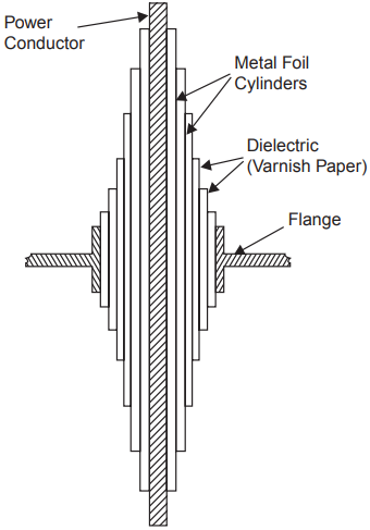
The capacitance of the capacitors formed by the metal foil cylinders is given by
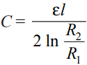
Where l is the axial length of the capacitor R1 and R2 are the radii of its cylindrical plates.
If these capacitors have the same capacitance, the potential difference between their plates will be equal. The equal capacitance between different layers is made possible by choosing a suitable axial length together with a ratio R2/R1.
With this strategy the potential gradient in the dielectric is uniform but the edges of the foil sheets lie on a curve, thus giving unequal surfaces of dielectric between the edges of successive sheets. This is undesirable as this would result in flashovers by “Creeping” along the surface.
However, if the differences between the lengths of successive sheets are made equal, the radial stress is not uniform and hence a compromise between the two conditions is usually adopted.
There are three types of papers used as insulating materials for capacitor bushings; oil-impregnated paper, resin-bonded paper, and resin-impregnated paper.
The oil-impregnated paper bushing is made by wrapping untreated paper after inserting foil sheets at the appropriate position and then impregnating it with transformer oil after vacuum drying. Before impregnation, it is ensured that moisture and air voids are avoided. This bushing can work at a radial stress of 40 kV/cm.
In the case of resin-impregnated bushing creped paper tape is wrapped around the conductor and then dried in an autoclave under controlled heat and vacuum. Epoxy resin is then sprayed to fill the winding. The permissible radial stress in this case is 30 kV/cm.
In the case of resin bonded paper bushing, the paper is first coated with epoxy resin and wrapped around a cylindrical form under heat and pressure after inserting foil sheets at the appropriate position. The permissible radial stress in this case is 20 kV/cm.
Application of Oil in Power Apparatus
Oil is normally used for providing insulation between the live parts of different phases and between phases and the grounded enclosure containing the oil and the main parts of the apparatus. Also, it provides a cooling effect to the apparatus placed within the enclosure.
Besides providing insulation, the oil helps the C.B. to quench the arc produced between the breaker contacts when they begin to separate to eliminate the faulted section from the healthy section of the system.
In an oil circuit breaker, the heat of the oil decomposes the oil which boils at 658 K. The gases liberated are approx. (i) Hydrogen, 70%, (ii) Acetylene, 20%, (iii) Methane, 5% and (iv) Ethane, 5%. (the abbreviation for these gases could be used as HAME).
The temperature of the arc is too high for the three last-named gases to exist and the arc itself runs into a mixture of hydrogen, carbon, and copper vapor at a temperature above 6000 K. The hydrogen being a diatomic gas gets dissociated into the atomic state which changes the characteristics of the arc on account of its associated change in its thermal conductivity. The outcome of this is that the discharge suddenly contracts and acquires an appreciably higher core temperature.
In certain cases, the thermal ionization may be so great that the discharge runs with a lower voltage which may stop the ionization due to the electric field strength. The transition from field ionization to thermal ionization is most marked in hydrogen and, therefore, in oil circuit breakers. The separation of the C.B. contacts which are carrying current gives rise to an arc without changing much the current wave form.
Initially when the contacts just begin to separate the magnitude of the current is very large but the contact resistance is very small, and a small voltage appears across them. But the distance of separation being very very small, a large voltage gradient is set up which is good enough to cause ionization of the particles between the contacts. Also, it is known that with the copper contacts which are generally used for the circuit breakers very little thermal ionization can occur at a temperature below the melting point. For effective field emission, the voltage gradient required is 106 V/cm.
From this, it is clear that the arc is initiated by the field emission rather than the thermal ionization. This high voltage gradient exists only for a fraction of a microsecond. But in this short period, a large number of electrons would have been liberated from the cathode and these electrons while reaching the anode, on their way would have collided with the atoms and molecules of the gases. Thus, each emitted electron tends to create others and these in turn derive energy from the field and multiply. In short, the work done by the initially emitted electrons enables the discharge to be maintained.
Finally, if the current is high, the discharge attains the form of an arc having a temperature high enough for thermal ionization, which results in a lower voltage gradient. Thus, an arc is initiated due to the field effect and then maintained due to thermal ionization.
Application of Gases in Power System
The gases find wide application in power systems to provide insulation to various equipment and substations. The gases are also used in circuit breakers for arc interruption besides providing insulation between breaker contacts and from contact to the enclosure used for contacts.
The various gases used are (i) air (ii) oxygen (iii) hydrogen (iv) nitrogen (v) CO2 and (vi) electronegative gases like sulfur hexafluoride, arcton, etc.
The various properties required for providing insulation and arc interruption are
- High dielectric strength.
- Thermal and chemical stability
- Non-inflammability
- High thermal conductivity. This assists in cooling current-carrying conductors immersed in the gas and also assists the arc-extinction process.
- Arc extinguishing ability. It should have a low dissociation temperature, a short thermal time constant (ratio of energy contained in an arc column at any instant to the rate of energy dissipation at the same instant), and should not produce conducting products such as carbon during arcing.
- Commercial availability at moderate cost.
Of the simple gases air is the cheapest and most widely used for circuit breaking. Hydrogen has better arc extinguishing properties but it has lower dielectric strength as compared with air. Also if hydrogen is contaminated with air, it forms an explosive mixture. Nitrogen has similar properties as air, and CO2 has almost the same dielectric strength as air but is a better arc-extinguishing medium at moderate currents. Oxygen is a good extinguishing medium but is chemically active. SF6 has outstanding arc-quenching properties and good dielectric strength. Of all these gases, SF6 and air are used in commercial gas blast circuit breakers.
Air at atmospheric pressure is ‘free’ but dry air costs a lot when stored at say 75 atmosphere. The compressed air supply system is a vital part of an air blast C.B. Moisture from the air is removed by refrigeration, by drying agents, or by storing at several times the working pressure and then expanding it to the working pressure for use in the C.B. The relative cost of storing the air reduces with increase in pressure. If the air to be used by the breaker is at 35 kg/cm2 it is common to store it at 210 kg/cm2. Air has an advantage over the electronegative gases in that air can be compressed to extremely high pressures at room temperature and then its dielectric strength even exceeds that of these gases.
The SF6 gas is toxic and its release in the form of leakage causes environmental problems. Therefore, the electrical industry has been looking for an alternative gas or a mixture of SF6 with some other gas as an insulating and arc-interrupting medium.
It has been observed that a suitable mixture of SF6 with N2 is a good replacement for SF6. This mixture is not only finding acceptability for providing insulation e.g., gas insulated substation and other equipment, it can quench high current magnitude arcs. The mixture is not only cost-effective, but it is less sensitive to find non-uniformities present within the equipment. The electric power industry is trying to find the optimum SF6 to N2 mixture ratio for various components of the system viz., GIS, C.B., capacitors, CT, PT, and cables.
A ratio of 70% of SF6 and 30% of N2 is found to be optimum for circuit breaking. With this ratio, the C.B. has a higher recovery rate than pure SF6 at the same partial pressure. The future of using SF6 with N2 or He for providing insulation and arc interruption is quite bright.
Related Posts
- Dia Para Ferro Magnetic Materials
- Applications of Soft and Hard Magnetic Materials
- Why CRGO core is used in transformers?
- Properties of High Resistivity Materials
- Properties of Insulating Materials
- Applications of Insulating Materials
- Properties of Superconductors
- Dielectric Strength | Constant | Loss | Definition
- Creep in Materials