In modern power systems, the power flow in the transmission lines can be controlled with the use of power electronics. The Flexible A.C. Transmission Systems (FACTS) give solutions to the problems and limitations that were introduced in the power system with the introduction of power electronics-based control for reactive power.
The FACTS technology making use of power electronics promotes the control of transmission lines. It also increases the load on the line up to the thermal limits without compromising reliability. The line capacity is thus increased which improves the reliability of the system. Due to this, there is maximum utilization of available equipment and additional bulk power transfers are possible. This also avoids the construction of new transmission lines which is time time-consuming process.
Flexible AC Transmission Systems | FACTS
The FACTS-based controllers give instantaneous control of transmission voltage and increase capacity providing larger flexibility in bulk power transmission. It also helps in damping out major grid oscillations. The advantages offered by FACTS-based controllers are given below.
- It controls line impedance angle and voltage which helps in controlling the power flow in transmission lines.
- The power flow in the transmission lines can be made optimum.
- It helps in damping out the oscillations and avoids damage to various equipment.
- It supports the power system security by increasing the transient stability limit It also limits overloads and short circuit currents.
- The reserve requirements for generators are considerably reduced as these controllers provide secure and controllable tie-line connections to neighboring electric utilities.
- The loading capacity of the line is greatly increased up to their thermal capabilities. Thus line upgradation is possible.
- It limits the impacts of faults and equipment failures.
- The reactive power flow in the lines can be decreased and the lines are made to carry more active power.
- There is an increase in the utilization of low-cost generation due to the cost-effective enhancement of transmission line capacity.
Objectives of Flexible AC Transmission Systems
The concept of FACTS was established to solve the problem that was emerging in power systems in the late 1980s as there were restrictions on the construction of transmission lines and to promote power growth of import and export. The main objectives behind the FACTS-based controllers are
- The power transfer capability of transmission systems is to be increased.
- The power flow is to be kept over the designated routes.
The first objective indicates that the power flow in a given transmission line can be increased up to its thermal limit. This can be achieved by passing the required current through the series line impedance and maintaining the stability of the system through the proper real-time control of power during and after system faults. The second objective indicates that the flow of power in the line can be restricted to select proper transmission corridors by controlling the current in the line.
If these two objectives are fulfilled then there will be a significant increase in the utilisation of new and existing transmission lines. It will promote the deregulation of the power system and there will be minimum requirements for new transmission lines. To implement these objectives, high-power compensators and controllers are required.
The concept of Flexible A.C. Transmission Systems (FACTS) was first defined in 1988 by N.G. Hingorani. These controllers control all the interrelated parameters that are involved in power system operation such as series and shunt impedance, current, voltage, and phase angle. Also, it damps the oscillations at various frequencies below the rated frequency. Thus these controllers are advantageous to power systems in terms of their operation, control, planning of lines, and finance.
Types of FACTS Controllers
There are a large number of types of FACTS controllers with the recent advancement in power systems. Some of these controllers are already installed and put in operation while some of them are still under construction. However, more work is to be carried out in this area so that new characteristics of these controllers can be fully used.
Presently FACTS highlights power flow control and modulation, operating devices, damping of oscillations, and stability enhancement. There are four main categories under which FACTS controllers are divided.
1. Series Controller: These types of controllers inject voltage in series with the line. The current flowing through the line multiplied by variable impedance represents injected series voltage in the line. Till the time the voltage is in phase quadrature with the line current, these controllers only supply variable reactive power. If there phase relationship between voltage and current is different then real power is also handled in addition to reactive power. A typical series FACTS controller is shown in Fig. 1.
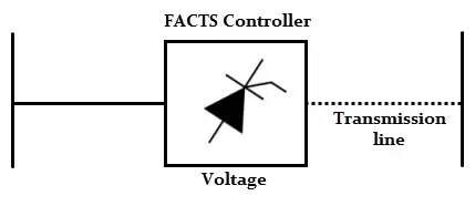
The series controller is normally of variable impedance types such as a capacitor, a reactor, or a power electronics-based variable source of main, subsynchronous, and harmonic frequencies to satisfy the requirement.
2. Shunt Controllers: The shunt controllers inject current into the system at the point of reconnection. The shunt controllers are of variable impedance type, variable source type, or a combination. The shunt type of FACTS controller is shown in the Fig. 2.
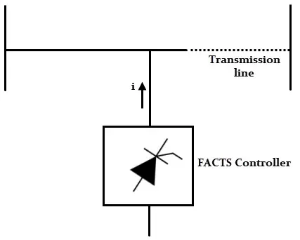
If a variable shunt impedance is connected to line voltage, variable current flows and current is injected in the line. So long as there is a quadrature relationship between voltage and current, these controllers either supply or deal with reactive power. For other phase relationships, active power is also handled.
3. Combined Series-Series Controllers: Such a type of controller is shown in the Fig. 3.
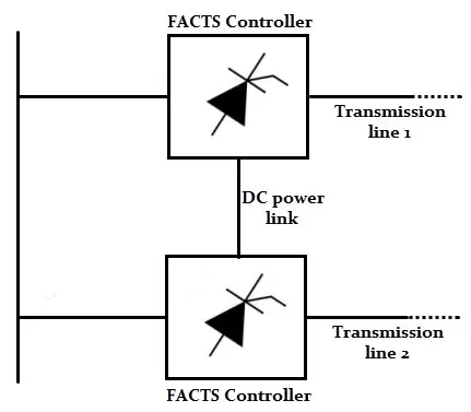
In these types of controllers, series controllers are controlled in a coordinated manner in the case of the multiline transmission system. It is alternatively a unified controller in which series controllers individually supply reactive power compensation independently for every line and also transfer real power among the lines through power links.
The meaning of the term unified indicates that the D.C. terminals of all the controller converters are connected for transferring real power. The capacity of these controllers to transfer real power makes maximized utilization of the transmission system as it is possible to balance both real and reactive power flow in the lines.
4. Combined Series-shunt Controllers: It may be a combination of separate series and shunt controllers which are controlled in a coordinated manner as shown in Fig. 4(a) or a unified power flow controller with series and shunt elements as shown in Fig. 4(b).
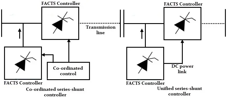
In these types of controllers, current is injected into the system through the shunt part of the controller while voltage is injected in the line through the series part of the controller. In the unified series-shunt controller, it is possible to exchange real power between series and shunt controllers through a D.C. power link.
FACTS Devices
In this section, various FACTS-based devices are listed. The various FACTS devices are given below.
- Static Synchronous Compensator (STATCOM).
- Static Synchronous Generator (SSG)
- Static VAR Compensator (SVC).
- Thyristorized switched or controlled reactor (TSR/TCR)
- Thyristor switched capacitor
- Static VAR Generator or absorber (SVG)
- Static VAR System (SVS)
- Thyristor Controlled Braking Resistor (TCBR)
- Static Synchronous Series Compensator (SSSC)
- Interline Power Flow Controller (IPFC)
- Thyristor-controlled or switched series capacitor or series reactor (TCSC/TSSC/TCSR/TSSR)
- Unified Power Flow controller (UPFC)
- Thyristor-controlled phase shifting transformer (TCPST)
- Interphase power controller (IPC)
- Thyristor-controlled voltage limiter (TCVL)
- Thyristor-controlled voltage regulator (TCVR)
Static Synchronous Compensator (STATCOM)
It is shunt connected static VAR compensator whose capacitive or inductive output current can be controlled independently of the a.c. system voltage. It is shown in the Fig. 5.
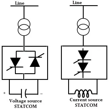
In the case of a voltage source converter, the A.C. output voltage is controlled in such a way that the proper reactive current will flow for any bus voltage. The D.C. capacitor voltage is automatically adjusted as per the requirement so that it acts as a voltage source for the converter. The harmonics in the system can be absorbed by designing STATCOM as an active filter.
It is a three-phase inverter driven by the voltage across the capacitor and the three-phase output voltages are in phase with A.C. system voltages. The difference in the amplitudes of the voltages gives how much current flows. The reactive power and its polarity can be changed by controlling the voltage.
The performance of STATCOM is better than SVC. With depression in voltage, STATCOM will still supply high reactive power by using its over-current capability. The large capacitor present acts as a storage device and can continue to deliver some energy for a short duration just like a synchronous condenser. The use of STATCOM needs Gate turn-off (GTO) thyristors which are costly as compared to normal thyristors.
Static VAR Compensator (SVC)
In STATCOM, converters are used while in SVC thyristors without gate turn-off capability are used. It is shunt connected static VAR generator or absorber. The output of SVC is adjusted to control capacitive or inductive current to control or maintain certain parameters, normally the magnitude of the bus voltage of the power systems. A basic model of SVC is shown in Fig. 6.
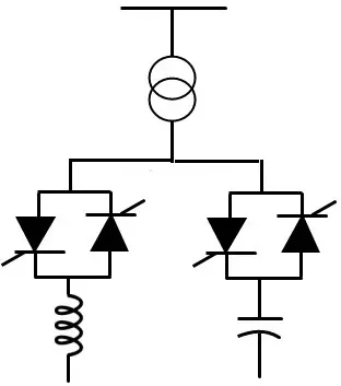
The separate types of equipment are present in SVC for lagging and leading VARS. It is a low-cost substitute for STATCOM. In STATCOM, the most reactive power that is delivered is a product of voltage and current whereas in the case of SVC, it is the square of voltage divided by the impedance. The reactive power capability steeply falls off as a function of the square of voltage in this case.
Comparison of STATCOM and SVC
The comparison between SVC and STATCOM is given in this section.
SVC
- Generation of more harmonics.
- During the transients, the performance is slow.
- Acting as a variable susceptance.
- Operates mainly in the capacitive region.
- Sensitive to transmission system harmonic resonance.
- Operation is difficult for a weak a.c. system.
STATCOM
- Generation of lesser harmonics.
- Better performance during transients and faster response.
- Acting as a voltage source behind a reactance.
- Operation in both inductive and capacitive regions is possible.
- Insensitive to transmission system harmonic resonance.
- With a very weak system, it can maintain a stable voltage.
Thyristor Controlled Series Capacitor (TSCS)
It is a capacitive reactance type of compensator consisting of a series capacitor bank connected in parallel with a thyristor-controlled reactor to provide smooth variable capacitive reactance. It is an important type of FACTS controller based on thyristors without the gate turn-off capability. It is shown in Fig. 7.
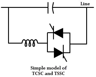
The thyristor-controlled reactor (TCR) is connected across a series capacitor. When the firing angle of TCR is 180°, the reactor is nonconducting and the series capacitor has its normal impedance. If the firing angle is decreased from 180°, the capacitive impedance increases. The reactor is fully conducting when the firing angle is 90°.
In this case, the total impedance is inductive as the designed value of the reactor impedance is less than the impedance of the series capacitor. The TCSC helps in limiting fault current for a firing angle of 90°. To get the best performance from TCSC, it has different-sized small capacitors or several equal capacitors instead of a single large unit.
Unified Power Flow Controller (UPFC)
It is a combination of a static synchronous compensator (STATCOM) and a static synchronous series compensator (SSSC). These two are coupled through a d.c. link and allows the bidirectional flow of real power between series output terminals of SSSC and shunt output terminals of the STATCOM. These can be controlled to provide real and reactive series line compensation without an external electrical energy source. It is shown in the Fig. 8.
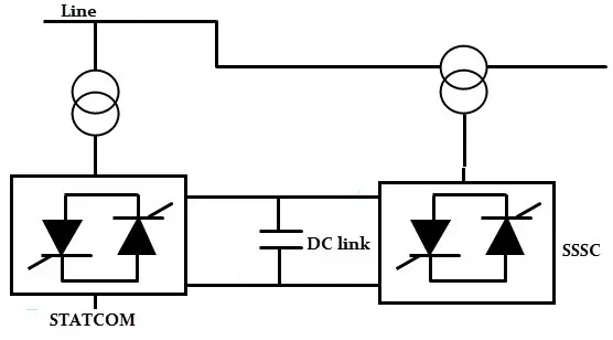
The meaning of UPFC is the angular, unconstrained injection of series voltage to control selectively the line voltage, impedance, and angle. Alternatively, real and reactive power flow in the line is controlled. The independent controllable shunt compensation is also provided by UPFC.