Voltage Distribution Over Suspension Insulator String
Suspension Insulators: As the voltage level increases, pin-type insulators become very bulky and their cost also increases rapidly. Hence the most popular insulators used for very high voltage transmission lines are suspension-type insulators. These insulators have several porcelain disc units. These units are connected in series with the help of metal links. This forms a string of porcelain discs.
The topmost insulator unit is connected to the cross arm of the tower while the lowest insulator is made to hold the conductor along the conductor shoe. Each unit is designed for the low voltage for say 11 kV but a string of such units gives us the proper insulation against very high voltage levels. The two important types of suspension type insulators are,
- Cemented cap type
- Hewlett or inter-linking type
The cemented cap type is the most commonly used suspension type insulator. It consists of a single disc-shaped piece of porcelain. At the bottom, it is grooved to increase the flash over distance. A galvanized cast iron cap is cemented at the top. The space is provided in the cap, which can be used to hold the pin of another unit. The cap is cemented to the insulator and the pin is either cemented or connected using a steel wire spring ring.
The main drawback of this type is that the cubical expansions of three materials iron, porcelain, and cement are different from each other, and due to this, fine cracks in the insulator may appear and early failure is possible.
The Hewlett-type insulator is more simple in design. It consists of a porcelain disc. The top portion of the disc consists of two curved tunnels, the planes of which are at right angles to each other. Lead-covered steel U links are passed through the tunnels. These links are bolted to the two similar units at the top and bottom. No cementing is required in this type of insulator.
The mechanical strength of this type is also very high due to the use of steel links. Another advantage of this type is that even if porcelain breaks due to the links, the units are held together and there is no interruption in the working.
But the main disadvantage of this type is that the porcelain in between is under high electrostatic stress and hence there is the possibility of puncture earlier than the cemented cap type. Hence cemented cap type is preferred over Hewlett type.
Advantages of Suspension Insulators
The various advantages of the suspension type insulators are,
- For higher voltages, these are cheaper than the pin insulator.
- Each unit is designed for low voltage levels such as 11 kV but by connecting such units in series to form a string, an insulator for any higher voltage level can be designed.
- In case of failure of any of the units, the replacement work can be done very easily and the entire string need not be replaced.
- If the line voltage is required to be increased at some later stage to satisfy increased load demand then just by adding additional units to the string, the same insulator can be used. Adding such units is very easy.
- This type of insulator provides greater flexibility to the line. The string is suspended and is free to swing in any direction. So it takes the position so that mechanical stresses on the line are minimum.
- When used with steel towers, the line conductors are less affected by lightning. This is because the conductor is lower than the earthed cross arm and the arrangement acts as a lightning arrester.
Strain Insulators
These insulators are used when there is a dead end of the line or corner or line is at a sharp curve or the line is crossing the river etc. These insulators reduce the excessive tension on the line under such abnormal conditions. For low voltage lines below 11 kV shakle insulators are used but for higher voltages strain insulators are used.
Assembaly of suspension insulators is used as strain insulators. The discs of strain insulators are in a vertical plane instead of the horizontal plane as in the suspension insulators. In case of conditions like a crossing of the river, there is excessive tension on the line. In such cases, two or more strings of the insulators are used in parallel.
Voltage Distribution Over Suspension Insulator String
Consider a string of suspension insulators. The number of porcelain discs are connected in series with the help of metal links. Fig. 1. shows a string of 4 porcelain disc suspension insulators.
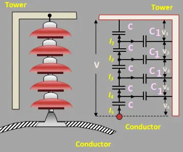
The porcelain portion which is an insulator is in between the two metal fittings. Thus it forms a capacitor. This is called “self-capacitance” or “mutual-capacitance”. Hence, the whole string shown in Fig. 1. consists of 4 such self-capacitors in series.
If only such a self or mutual capacitor existed alone in series, the voltage across them would have been equal and the series charging current through them would have been the same.
But in addition to the self capacitances, there will be capacitance between each metal fitting and the earth i.e. tower. The air acts as a dielectric. Such a capacitance is called “shunt capacitance”.
Due to shunt capacitors, the charging current no longer remains the same.
The different currents, mutual capacitors, and shunt capacitors are shown in Fig. 2. The mutual capacitors are denoted as C while the shunt capacitors are denoted as C1.
Assuming the design of each section of the string same, the mutual capacitors are assumed equal. Similarly, all shunt capacitors are also assumed equal.
There will be capacitance between metal fittings and the line conductor. But its value is very small and generally, it is neglected.
The currents I1, 12, 13, and 14 are charging currents flowing through mutual capacitors while i1, i2, i3, and i4 are the currents flowing through the shunt capacitors. Due to the different charging currents, each capacitor will get charged to a different potential. Hence the voltage across each section of the string will be different. It is shown as V1, V2, V3, and V4 in Fig. 2.
As the charging current is highest nearest to the line conductor, the voltage across the capacitor nearest to the line conductor will be maximum. Thus V4 will be the maximum, for the case considered. Hence the insulator adjacent to the line conductor is under maximum electrical stress and is liable to puncture. The following observations can be made related to the voltage distribution over a string of suspension insulators :
- The voltage distribution is not uniform due to shunt capacitors.
- The charging currents through various mutual capacitors are different.
- The voltage across the top unit farthest from the line conductor is the lowest.
- The voltage across the bottom unit which is adjacent to the line conductor is maximum.
- Due to the maximum voltage impressed on the insulator nearest to the line conductor, it is under maximum electrical stress.
- Due to maximum electrical stress, the insulator nearest to the line conductor is likely to puncture. Hence practical efforts are made to have uniform voltage distribution as far as possible.
- In the case of d.c. voltage, the capacitors do not play any role and the voltage distribution is uniform.
String Efficiency of Suspension Insulators
The nonuniformity in the voltage distribution over a string of suspension insulators is expressed in terms of a parameter called “string efficiency”. The string efficiency is defined as the ratio of total voltage across the string to the product of the number of units and the voltage across the unit adjacent to the line conductor. Mathematically it can be expressed as,
String Efficiency = Voltage across the string ÷ n x voltage across the unit adjacent to the line conductor
Where n = number of units or discs in the string.
The string efficiency is calculated based on the string used for each line and hence the voltage across the string is the voltage of the conductor with respect to earth i.e. phase voltage. The higher the value of the string efficiency, the more uniform the voltage distribution across the string.
For the ideal case, the string efficiency is 100% and the voltage across each disc of the string is equal. Practically various methods are used to obtain the string efficiency as high as possible. In the rainy season, insulators are wet, and the mutual capacitance value increases. Thus the ratio of shunt to mutual capacitance i.e. k decreases. This increases the uniformity of the voltage distribution. Hence in the rainy season, string efficiency is higher.
Methods of Increasing String Efficiency
We have seen that the higher the value of the string efficiency, the more uniform the potential distribution over a string of suspension insulators. The line unit is always under the maximum electrical stress. To avoid the possibility of puncture of line unit due to excessive stress, efforts are made to have uniform potential distribution. Hence some methods are used in practice to get higher string efficiency. These methods are,
- Reducing the ratio of shunt-capacitance to self-capacitance
- By grading the insulators
- Use of a guard ring to provide static shielding
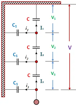
1. Reducing the Ratio of Shunt Capacitance to Self Capacitance: The voltage across the line unit depends on the value of k which is the ratio of shunt capacitance to self capacitance. The string efficiency is dependent on the voltage across the line unit. The lower the value of k, the higher the string efficiency, and the more uniform is the potential distribution. The voltages across the various units of string are almost equal for very low values of k.
Now k = C1/C i.e. the ratio of shunt capacitance to self capacitance. So to reduce the value of k, C1 must be reduced. This is possible by increasing the distance between the insulator and the earth i.e. tower.
This can be achieved by increasing the length of cross-arms. The more the length of the cross-arm, the less is the value of C1 and less is the value of k. But this method has practical limitations such as:
- The use of long cross-arm increases the cost.
- Due to the long cross-arm overall strength of the tower reduces.
Hence in practice, the minimum value k which can be achieved by this method is 0.1. Due to these limitations, this method is rarely used in practice.
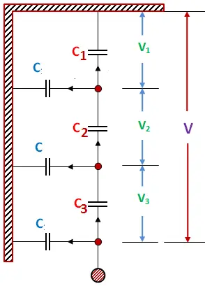
2. Grading the Insulators: By correct grading of the insulators, more uniform voltage distribution across the string can be achieved. In the method of grading, the insulators are so selected that the self capacitances i.e. mutual capacitance of the various units are different and the values of mutual capacitances decrease from the line unit towards the top unit.
So top unit has minimum mutual capacitance while the line unit has maximum mutual capacitance. The voltage for the given current across the capacitance is inversely proportional to the capacitance. So the more the capacitance, the lesser the voltage across the capacitance.
Thus keeping line unit capacitance to be maximum, current through it is minimum. This reduces the voltage across the line unit.
So by properly grading the insulators i.e. by using different sized insulators in a string, uniform voltage distribution can be achieved and string efficiency can be improved. The grading is shown in Fig. 3.
The design of such string using different-sized insulators is practically complicated and inconvenient. Hence the method is used only for very high voltage systems such as 200 kV and above. Though the design of such string is inconvenient, using standard insulators for most of the units and larger units adjacent to the line conductor, better results can be obtained.
3. Use of Guard Ring: In this method, a large metal ring surrounding the line unit and connected to the metal part of the bottom of the line unit is used. Such a ring is called a “guard ring”. The guard ring is shown in Fig. 4. This is also called static shielding of the string.
Earlier it was mentioned that capacitance between the insulator and the line is neglected but the use of a guard ring increases the capacitance between the metal part of the insulator and the line.
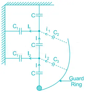
These capacitances are shown as C2 and C3 in Fig. 7.15. These capacitances are greater for the lower units. Due to this, the voltage across these units is reduced. An equal distribution of voltage is not possible by this method.
But the guard ring used can be designed in such a way that shunt capacitance currents I1, I2, I3, etc. are equal to the currents through the newly introduced capacitors i.e. i1, i2, i3, etc. as shown in Fig. 4.
Due to this, the charging current through the mutual capacitors remains the same, giving uniform voltage distribution. But such a design is practically difficult. Thus the primary aim of the guard ring is to reduce the electrical stress on the lower units.