Discrete I/O Modules of PLC
The most common type of I/O interface module is the discrete type ( Figure 1). This type of interface connects field input devices of the ON/OFF nature such as selector switches, pushbuttons, and limit switches. Likewise, output control is limited to devices such as lights, relays, solenoids, and motor starters that require simple ON/OFF switching.
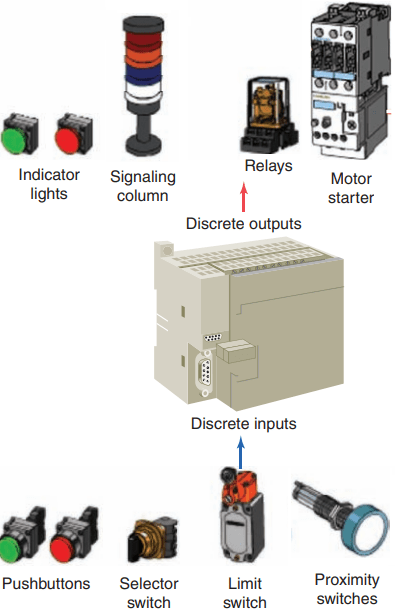
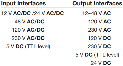
The classification of discrete I/O covers bit-oriented inputs and outputs. In this type of input or output, each bit represents a complete information element in itself and provides the status of some external contact or advises of the presence or absence of power in a process circuit. Each discrete I/O module is powered by some field-supplied voltage source. Since these voltages can be of different magnitude or type, I/O modules are available at various AC and DC voltage ratings, as listed in Table 1.
I/O Interface Modules
The modules themselves receive their voltage and current for proper operation from the backplane of the rack enclosure into which they are inserted.
Backplane power is provided by the PLC module power supply and is used to power the electronics that reside on the I/O module circuit board. The relatively higher currents required by the loads of an output module are normally provided by user-supplied power.
Module power supplies typically may be rated for 3 A, 4 A, 12 A, or 16 A depending on the type and number of modules used. Figure 2 shows the block diagrams for one input of a typical alternating current (AC) discrete input module.
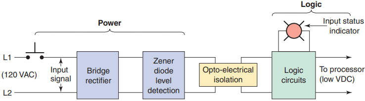
The input circuit is composed of two basic sections: the power section and the logic section. An optical isolator is used to provide electrical isolation between the field wiring and the PLC backplane internal circuitry. The input LED turns on or off, indicating the status of the input device. Logic circuits process the digital signal to the processor. Internal PLC control circuitry typically operates at 5 VDC or less volts.
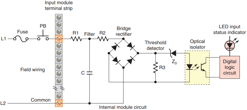
A simplified diagram for a single input of a discrete AC input module is shown in Figure 3. The operation of the circuit can be summarized as follows:
- The input noise filter consisting of the capacitor and resistors R1 and R2 removes false signals that are due to contact bounce or electrical interference.
- When the pushbutton is closed, 120 VAC is applied to the bridge rectifier input.
- This results in a low-level DC output voltage that is applied across the LED of the optical isolator.
- The zener diode (ZD ) voltage rating sets the minimum threshold level of voltage that can be detected.
- When light from the LED strikes the phototransistor, it switches into conduction and the status of the pushbutton is communicated in logic to the processor.
- The optical isolator not only separates the higher AC input voltage from the logic circuits but also prevents damage to the processor due to line voltage transients. In addition, this isolation also helps reduce the effects of electrical noise, common in the industrial environment, which can cause erratic operation of the processor.
- For fault diagnosis, an input state LED indicator is on when the input pushbutton is closed. This indicator may be wired on either side of the optical isolator.
- An AC/DC type of input module is used for both AC and DC inputs as the input polarity does not matter.
- A PLC input module will have either all inputs isolated from each other with no common input connections or groups of inputs that share a common connection.
Discrete I/O Modules of PLC
Discrete input modules perform four tasks in the PLC control system. They:
- Sense when a signal is received from a field device.
- Convert the input signal to the correct voltage level for the particular PLC.
- Isolate the PLC from fluctuations in the input signal’s voltage or current.
- Send a signal to the processor indicating which sensor originated the signal.
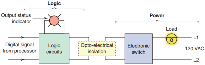
Figure 4 shows the block diagram for one output of a typical discrete output module. Like the input module, it is composed of two basic sections: the power section and the logic section, coupled by an isolation circuit.
The output interface can be thought of as an electronic switch that turns the output load device on and off. Logic circuits determine the output status. An output LED indicates the status of the output signal.
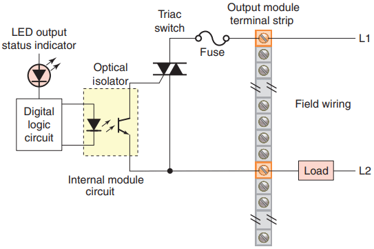
A simplified diagram for a single output of a discrete AC output module is shown in Figure 5 . The operation of the circuit can be summarized as follows:
- As part of its normal operation, the digital logic circuits of the processor set the output status according to the program.
- When the processor calls for an output load to be energized, a voltage is applied across the LED of the opto-isolator.
- The LED then emits light, which switches the phototransistor into conduction.
- This in turn triggers the triac AC semiconductor switch into conduction allowing current to flow to the output load.
- Since the triac conducts in either direction, the output to the load is alternating current.
- The triac, rather than having ON and OFF status, actually has LOW and HIGH resistance levels, respectively. In its OFF state (HIGH resistance), a small leakage current of a few milliamperes still flows through the triac.
- As with input circuits, the output interface is usually provided with LEDs that indicate the status of each output.
- Fuses are normally required for the output module, and they are provided on a per circuit basis, thus allowing for each circuit to be protected and operated separately. Some modules also provide visual indicators for fuse status.
- The triac cannot be used to switch a DC load.
- For fault diagnosis, the LED output status indicator is on whenever the PLC is commanding that the output load be switched on.
Individual AC outputs are usually limited by the size of the triac to 1 A or 2 A. The maximum current load for any one module is also specified. To protect the output module circuits, specified current ratings should not be exceeded.
For controlling larger loads, such as large motors, a standard control relay is connected to the output module. The contacts of the relay can then be used to control a larger load or motor starter. When a control relay is used in this manner, it is called an interposing relay.
Discrete output modules are used to turn field output devices either on or off. These modules can be used to control any two-state device, and they are available in AC and DC versions and in various voltage ranges and current ratings.
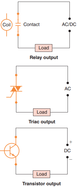
Output modules can be purchased with transistor, triac, or relay output as illustrated in Figure 6.
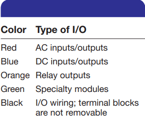
Triac outputs can be used only for control of AC devices whereas transistor outputs can be used only for control of DC devices. The discrete relay contact output module uses electromechanical as the switching element. These relay outputs can be used with AC or DC devices, but they have a much slower switching time compared to solidstate outputs. Allen-Bradley modules are color-coded for identification as follows:
Sourcing and Sinking I/O Modules of PLC
Certain DC I/O modules specify whether the module is designed for interfacing with current-source or current-sink devices. If the module is a current-sourcing module, then the input or output device must be a current-sinking device. Conversely, if the module is specified as current-sinking, then the connected device must be current-sourcing.
Some modules allow the user to select whether the module will act as current sinking or current sourcing, thereby allowing it to be set to whatever the field devices require. The internal circuitry of some field devices requires that they be used in sinking or sourcing circuits.
In general, sinking (NPN) and sourcing (PNP) are terms used to describe a current signal flow relationship between field input and output devices in a control system and their power supply.
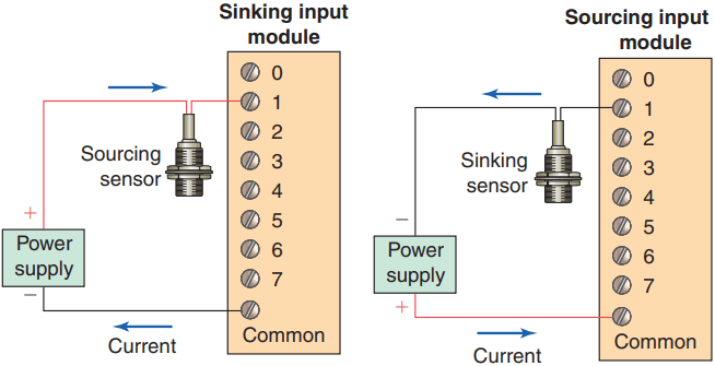
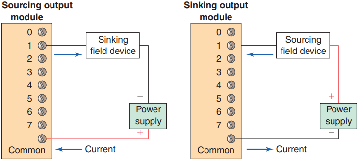
Figure 7 illustrates the current flow relationship between sinking and sourcing inputs to a DC input module. Figure 8 illustrates the current flow relationship between sinking and sourcing outputs to a DC output module.
DC input and output circuits are commonly connected with field devices that have some form of internal solid-state circuitry that needs a DC signal voltage to function.
Field devices connected to the positive side of the field power supply are classified as sourcing field devices. Conversely, field devices connected to the negative side or DC common of the field power supply are sinking field devices.
Thanks for reading about “discrete I/O modules of plc”.