The insulation resistance test of transformer complements other transformer tests. The solid winding insulation tests are not conclusive in themselves but provide valuable information on winding conditions, such as moisture content, and carbonization.
These tests are considered non-destructive even though at times they may cause a winding failure. It should be pointed out that a winding failure results from an incipient failure that the test was supposed to detect. If it had gone undetected, it might have occurred at an unplanned time.
Insulation Resistance Test of Transformer
This test is performed at or above rated voltage to determine if there are low resistance paths to the ground or between winding to winding as a result of winding insulation deterioration.
The test measurement values are affected by variables such as temperature, humidity, test voltage, and size of the transformer.
This test should be conducted before and after repair or when maintenance is performed. The test data should be recorded for future comparative purposes. The test values should be normalized to 20°C for comparison purposes.
The general rule of thumb that is used for acceptable values for safe energization is 1 MΩ per 1000 V of applied test voltage plus 1 MΩ. Sample resistance values of good insulation systems are shown in following Table.

Transformers
The test procedures are as follows:
- Do not disconnect the ground connection to the transformer tank and core. Make sure that the transformer tank and core are grounded.
- Disconnect all high-voltage, low-voltage, and neutral connections, lightning arresters, fan systems, meters, or any low-voltage control systems that are connected to the transformer winding.
- Before beginning the test, jumper together all high-voltage bushings, making sure that the jumpers are clear of all metal and grounded parts. Also jumper together all low-voltage and neutral bushings, making sure jumpers are clear of all metal and grounded parts.
- Use a megohmmeter with a minimum scale of 20,000 MΩ.
- Resistance measurements are then made between each set of windings and ground. The windings that are to be measured must have their ground removed to measure their insulation resistance.
- Megohmmeter reading should be maintained for 1 min. Make the following readings for two-winding transformers:
- High-voltage winding to low-voltage winding and to ground.
- High-voltage winding to ground.
- Low-voltage winding to high-voltage winding and to ground.
- Low-voltage winding to ground.
- High-voltage winding to low-voltage winding.


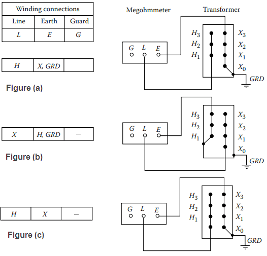
For three-winding transformers, the test should be made as follows:
- High to low, tertiary and ground (H-LTG), shown in Figure (a).
- Tertiary to high, low and ground (T-HLG).
- Low to high, tertiary and ground (L-HTG), shown in Figure (b).
- High, low, and tertiary to the ground (HLT-G).
- High and tertiary to low and ground (HT-LG), shown in Figure (c).
- Low and tertiary to high and ground (LT-HG).
- High and low to tertiary and ground (HL-TG).
Megohmmeter readings should be recorded along with the test temperature (°C). The readings should be corrected to 20°C by the correction factors.
If the corrected field test values are one-half or more of the factory insulation readings or 1000 MΩ, whichever is less, the transformer insulation system is considered safe for a hi-pot test.
Do not make the megohm test of the transformer winding without the transformer liquid because the values of insulation resistance in the air will be much less than in the liquid. Also, do not make the insulation resistance test of the transformer when it is under vacuum because of the possibility of flashover to the ground.
Acceptable insulation resistance values for dry and compound-filled transformers should be comparable to those for Class A rotating machinery, although no standard minimum values are available.
Oil-filled transformers or voltage regulators present a special problem in that the condition of the oil has a marked influence on the insulation resistance of the windings.
In the absence of more reliable data, the following formula is suggested:
IR = CE ÷ √kVA
Where, IR is the minimum 1 min 500 V DC insulation resistance in megohms from winding to ground, with other winding or windings guarded, or from winding to winding with core guarded.
C is a constant for 20°C measurements.
E is the voltage rating of winding under test kVA is the rated capacity of winding under test.

This formula is intended for single-phase transformers. If the transformer under test is one of the three-phase type, and the three individual windings are being tested as one, then E is the voltage rating of one of the single-phase windings (phase to phase for delta connected units and phase to neutral or star connected units) kVA is the rated capacity of the completed three-phase winding under test.
Dielectric Absorption Test
The dielectric absorption test is an extension of the transformer winding insulation resistance measurement test. The dielectric absorption test is conducted at voltages much higher than the usual insulation resistance test values and can exceed 100 kV. The test is evaluated on the basis of insulation resistance. If insulation is in good condition, the apparent insulation resistance will increase as the test progresses.
The test consists of applying voltage for 10 min and taking readings of resistance measurements at 1 min intervals. The resistance values measured during this test are plotted on log-log paper with coordinates of resistance versus time.
The slope of the curve for a good insulation system is a straight line increasing with respect to time, whereas a poor insulation system will have a curve that flattens out with respect to time.
Two tests are conducted under the dielectric absorption test. These are the dielectric absorption ratio test (DAR test) and the polarization index (PI) test.
DAR Test: A good insulation system shows a continued increase in its resistance value over the period of time in which voltage is applied. On the other hand, an insulation system that is contaminated with moisture, dirt, and the like will show a low resistance value.
In good insulation, the effect of absorption current decreases as time increases. In bad insulation, the absorption effect is kept alive by high leakage current.
This method is independent of temperature and equipment size. It can provide conclusive results as to the condition of the insulation. The ratio of time-resistance readings can be used to indicate the condition of the insulation system. The ratio of a 60 second reading to a 30 second reading is called the DAR
DAR = Resistance reading at 60s ÷ Resistance reading at 30s
A DAR ratio below 1.25 is the cause for investigation and possible repair of the electrical apparatus. Usually, the DAR readings are confined to the hand-driven megohmmeter.
PI Test: The PI test is a specialized application of the dielectric absorption test. The PI is the ratio of the insulation resistance at 10 min to the insulation resistance at 1 min. A PI of less than 1 indicates equipment deterioration and the need for immediate maintenance. This test is used for dry insulation systems such as dry-type transformers, cables, rotating machines, etc.
DC High-Potential Test of Transformer
The DC hi-pot test is applied at above the rated voltage of a transformer to evaluate the condition of winding insulation. The DC high-voltage test is not recommended on power transformers above 34.5 kV; instead, the AC hi-pot test should be used.
Generally, for routine maintenance of transformers, this test is not employed because of the possibility of damage to the winding insulation. However, this test is made for acceptance and after repair of transformers.
The DC hi-pot test can be applied as a step-voltage test where readings of leakage current are taken for each step. If the excessive leakage current is noticed, the voltage can be backed off before further damage takes place. For this reason, the DC hi-pot test is considered to be a nondestructive test.

of Liquid-Filled Transformers
The DC hi-pot test voltages are shown in above Table. The procedure for conducting this test is as follows:

- The transformer must have passed the insulation resistance test immediately prior to starting this test.
- Make sure the transformer case and core are grounded.
- Disconnect all high-voltage, low-voltage, and neutral connections, low-voltage control systems, fan systems, and meters connected to the transformer winding and core.
- Short-circuit with jumpers together all high-voltage bushings and all low-voltage bushings to the ground.
- Connect hi-pot test set between high-voltage winding and ground. Gradually increase test voltage to the desired value. Allow test voltage duration of 1 min, after which gradually decrease voltage to zero.
- Remove low-voltage to ground jumper and connect hi-pot test set between low-voltage winding and ground. Also, connect the short-circuited high-voltage winding to the ground. Gradually increase test voltage to the desired value. Allow the test voltage duration of 1 min, after which gradually decrease voltage to zero.
- If the preceding two tests do not produce breakdowns or failures, the transformer is considered satisfactory and can be energized.
Remove all jumpers and reconnect primary and secondary connections and other system equipment that may have been disconnected.
In liquid-filled transformers two insulation systems are in series, that is, solid insulation with oil or synthetic fluid. When using DC hi-pot test voltage on liquid-filled transformers, the solid insulation may be overstressed. Insulation that may be weakened near the neutral may remain in service due to lower stress under operating conditions. However, when subjected to hi-pot test voltage, it may break down and require immediate repair.
Thanks for reading about “insulation resistance test of transformer”.
Excellent document to learn about testing oil-immersed transformers