Characteristics of Strain Gauges
The core element of a piezoresistive sensor is the strain gauge. The characteristics of a strain gauge are mainly defined by the gauge dimensions, resistance, gauge factor, temperature coefficient, resistivity, and thermal stability.
Gauge dimensions and shape are very important in choosing a right type of strain gauge for a given application.
Gauge resistance is defined as the electrical resistance measured between two metal tabs or leads. Gauge resistance is an important design and application parameter since it determines both the output signal amplitude of the gauge (ΔV/V = ΔR/R) and the dissipation power (V2/R).
Gauge factor or strain sensitivity is defined as the ratio of (ΔR/R) and the strain ε. The real GF plots of common gauge materials are shown in Figure 1, where the GF is the slope of the curve.
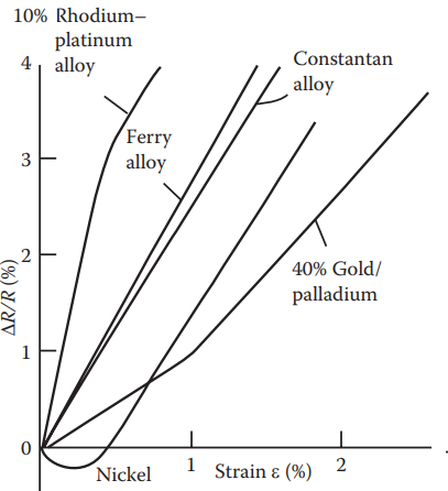
Both Ferry alloys and Constantan alloys have relatively high and constant GF values, indicating a well-behaved and consistent pattern.
The 10% rhodium–platinum alloy exhibits a desirable and high GF feature between 0% and 0.4% range of strain ε, but its performance degrades above 0.4% strain ε point.
Pure nickel even demonstrates a negative GF for small strain (ε < 0.5%).
The GF values of semiconductor materials are much larger than the GF values of metals. Therefore, the majority of piezoresistive strain gauges used today are made of semiconductor materials.
Type of Strain Gauge | Gauge Factor (GF) |
Metal foil | 1 – 5 |
Thin-film metal | ≈ 2 |
Bar semiconductor | 80 – 150 |
Diffused semiconductor | 80 – 200 |
The aboveTable gives the typical GF range of main types of strain gauges.
Hysteresis of a strain gauge is defined as the ratio (in percent) of the difference between the output signals of the gauge divided by the maximum output signal. The output signals of the gauge are obtained with increasing and decreasing strain loading at identical strain values.
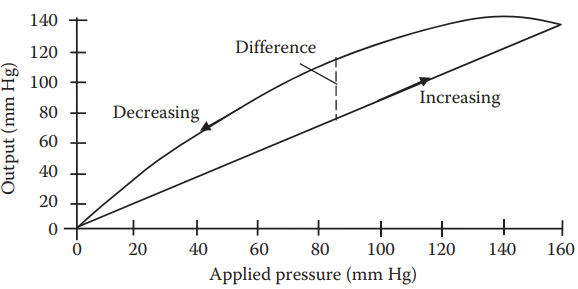
Above Figure 2, shows the hysteresis of a strain-gauge-type blood pressure sensor.
Creep is defined as the relative variation of the measured strain over time, Δt, when the gauge is under a constant stress:
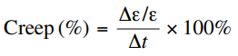
Creep is caused by the nonideal elastic behaviors of piezoresistors and adhesive materials when bonded to the measured object. Most gauges can be adjusted in design to exhibit either a positive or a negative creep under load. Spring element materials in piezoresistive sensors exhibit only positive creep under load.
Temperature characteristics of strain gauges are often described by two coefficients:
Temperature coefficient of resistance (TCR), defined as the relative resistance variation of the measuring element per degree of temperature variation:
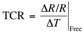
“Free” means the measuring element is unbounded or unembedded into any other material. TCR is an intrinsic characteristic of the gauge material; hence it is a basic design criterion.
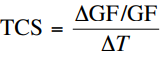
Temperature coefficient of sensitivity (TCS), defined as the relative variation of the gauge factor GF per degree of temperature variation:
Other Characteristics of Strain Gauges
Other characteristics of strain gauges include
- maximum permitted RMS excitation voltage (the maximum RMS value of the applied voltage),
- maximum elongation (the strain value at which the linearity deviation exceeds ±5%),
- linearity (the maximum difference between the actual output signal and the ideal output signal under the same strain),
- resolution (the smallest strain variation that can be resolved by the gauge),
- fatigue life (the number of load cycles supported by the gauge without significantly changing its characteristics),
- frequency response (the maximum sinusoidal strain variation frequency that can be resolved by the gauge),
- and smallest bending radius (the smallest value of the radius that the gauge will withstand in bending in one direction without significant changes in its characteristics).
Other important characteristics that must be considered when selecting a strain gauge include its stability. This is because the most desirable strain gauge materials are also sensitive to temperature variations and tend to change resistance as they age. Therefore, temperature and drift compensation must be included in many strain gauges.
Types of Strain Gauges
Types of strain gauges include wire strain gauges, foil strain gauges, single-crystal semiconductor strain gauges, and thin-film strain gauges.
Wire Strain Gauges: A wire strain gauge is the original type of resistive strain gauge. The first bonded, metallic wire-type strain gauges were developed in 1938. They are still extensively used in high-temperature environments today.
The wire is made of metals or their alloys with a typical diameter of 6 to 30 μm. Common wire materials are CrNi alloys for standard applications and PtW alloys for high-temperature applications.
The measuring grid is made by either flat winding or wrapping around a metallic wire, and is then bonded to, or completely embedded in, the substrate or carrier. The carrier or backing materials are reinforced epoxies (for standard applications), selfadhesive glass fiber-reinforced Teflon (“peel-off” backing, for high-temperature applications), and sheet brass or polycarbonate (for encapsulated strain gauges in rough ambient conditions).
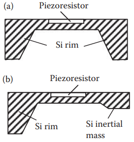
Metal Foil Strain Gauges: A foil strain gauge (see Figure 3) is the most widely used type. A very thin metal foil pattern (2 to 5 μm thick, usually Constantan or Nichrome V) is deposited onto a thin insulating backing or carrier (10to 30 μm thick, usually epoxy, polyimide, or polycarbonate). The measuring grid pattern including the metallic terminal tabs is produced by the photoetching process. The entire gauge is typically 5 to 15 mm long.
The main advantages of foil strain gauges over wire gauges are their better heat dissipation, low transverse sensitivity, better flexibility (the smallest bending radius is 0.3 mm), and easy creep compensation (the positive creep of the elastic sensing element can be compensated by the negative creep of the carrier material of the gauge).
The disadvantages include limited working temperature due to properties of the carrier materials and adhesives, as well as technical limitations in miniaturization.
Single-Crystal Semiconductor Strain Gauges: This type of strain gauge is manufactured from a thin strip of semiconductor cut from a single crystal of silicon or germanium, doped with accurate amounts of impurities to obtain either n- or p-type.
The output of a semiconductor gauge is very high compared to a wire or foil gauge. Semiconductor gauges can provide both positive and negative gauge factors depending on whether the gauges are n-type or p-type. The typical gauge factor of a semiconductor is −100 to +170, although −115 to +205 are achievable.
The output of semiconductor gauges is usually nonlinear with strain (p-type gauges have better linearity in tension while n-type gauges are more linear in compression), but they exhibit no creep or hysteresis and have an extremely long fatigue life.
Semiconductor gauges are highly sensitive to temperature; thus they require a high level of temperature compensation. They also present large TCR due to their specific resistance–temperature curves.
Semiconductor gauges are widely used in small sensors such as force, acceleration, and pressure sensors since their sensing elements can be micromachined out of a single piece of silicon.
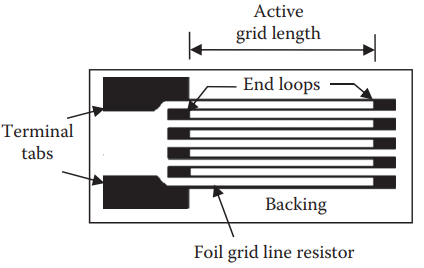
Thin-Film Strain Gauges: In thin-film strain gauges, the thin film (resistance element) is produced by sputtering or evaporating metals, alloys, or semiconductors (silicon or germanium) onto the carrier material (as a substrate) in vacuum.
Several stages of sputtering and evaporation may be needed to form up to eight layers of material in thin-film polycrystalline structure. The whole surface is finally coated with an appropriate sealant.
The final properties of the thin film are strongly influenced by various parameters of the deposition process (e.g., ultimate vacuum, substrate temperature, and rate of film growth). These processes are highly cost effective when strain gauges are produced in large quantities.
The structure of a thin-film gauge is shown in Figure 4. The gauge factor of a thin-film strain gauge is higher than those of wire or foil gauges, but lower than those of single-crystal semiconductor gauges. For instance, a germanium thin-film strain gauge has a GF of 32 to 39.
Type of Strain Gauge | Nominal Resistance |
Wire gauge | 60 ~ 350 Ω |
Foil or semiconductor gauge | 120 Ω ~ 5 kΩ |
Thin-film gauge | ~ 10 kΩ |
Supporting Structure of Strain Gauges
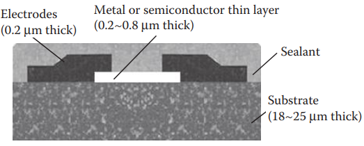
There are two main structures for holding piezoresistive sensing elements: membrane type (Figure 5a, typically in pressure and flow sensors) and cantilever beam type (Figure 5b, typically in acceleration sensors). A membrane-type sensor consists of a thin silicon membrane or plate with a load (e.g., pressure) differential across the plate.
The resulting deformation causes strain along the edges of the plate. Usually the plate, supported by a thicker silicon rim, is fabricated by etching away the bulk silicon in a defined region until the required thickness is reached. Both monocrystalline and polycrystalline silicon can be used for membranes.
With careful design, regions along the edge of the plate can be “doped” to create resistors, which will subsequently exhibit resistance change in proportion to the applied strain.
Most sensors with square membranes have four or more piezoresistors positioned at the four edges of the membrane and as close to the edge center as possible (see Figure 6) where the stresses are maximal.
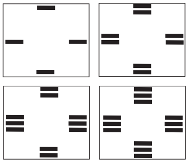
From this central point, stress drops more rapidly toward the center of the membrane than toward the corners. Thus perpendicularly placed (relative to the edge) piezoresistors are less sensitive than the parallelly placed ones.
In beam-type sensors, the stress caused by deflection of the inertial mass under a measurand (e.g., acceleration) is concentrated on the surface of the beam, where piezoresistors are placed.
Bonding Methods of Strain Gauges
Figure 7 shows four bonding methods for strain gauge: (a) adhesive bonding with backing, (b) adhesive bonding without backing, (c) deposited molecular bonding, and (d) diffused molecular bonding.
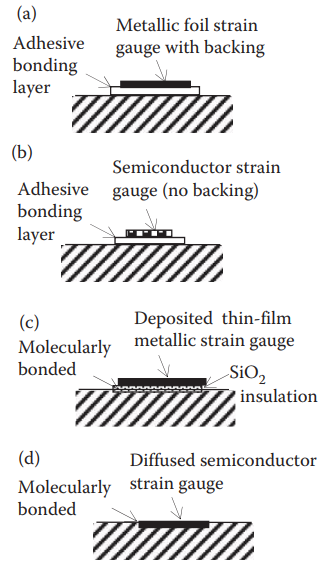
In Figure 7a, a metallic foil strain gauge is directly bonded to a strained surface through a thin layer of epoxy resin. The backing and the adhesive agent work together to transmit strain. The adhesive also serves as an electrical insulator between the foil grid and the strained surface.
A semiconductor gauge usually has no backing; therefore, it is diffused to the substrate and is then bonded to the strained surface with a thin layer of epoxy (Figure 7b). It is smaller and lower in cost than a metallic foil sensor. The epoxy used to attach foil gauges can also be used to bond semiconductor gauges.
A thin-film metallic strain gauge is molecularly bonded to the specimen (Figure 7c) by first depositing an electrical insulation (typically a ceramic) onto the stressed metal surface, and then depositing the strain gauge onto this insulation layer. This results in a much more stable installation with less resistance drift. The errors due to creep and hysteresis therefore are also eliminated.
The diffused (or embedded) semiconductor strain gauge also eliminates the need for an adhesive bonding agent (Figure 7d). It uses photolithography masking techniques and solid-state diffusion of boron to molecularly bond the resistance elements.
The resistance change of piezoresistive gauges is typically measured using a balanced Wheatstone bridge. This allows a small change in resistance to be measured relative to an initial zero resistance value in a balanced bridge, rather than to a large initial resistance value, which greatly improves sensitivity, accuracy, and resolution. My another article gives the details of a piezoresistive sensor measurement using bridge circuits.
Applications of Strain Gauges
Piezoresistive strain gauges are the most widely used sensors among all types of strain gauges. Piezoresistive strain gauges are applied in measuring acceleration, force, torque, pressure, and vibration.
Capacitive and inductive strain gauges’ sensitivity to vibration, the special mounting requirements, and circuit complexity have limited their applications. Photoelectric strain gauges are costly and delicate although they can be made as small as 1/16 inch in length.
Piezoresistive Accelerometers: A piezoresistive accelerometer usually contains a mass-spring system designed so that the force exerted by the spring exactly equals the force required to accelerate the mass, and the displacement of the mass (deflection) is directly proportional to the acceleration measured by the strain gauge.
Other common methods for measuring the deflection of the inertial mass are capacitive (measuring the gap between a movable electrode and a fixed electrode) and piezoelectric methods (measuring the produced voltage).
Figure 8 shows two piezoresistive accelerometers developed by Honeywell Sensotec, Columbus, Ohio.
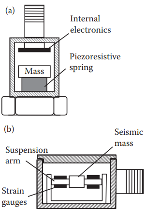
The first one (Figure 8a) uses a piezoresistive spring, where the force exerted by the mass changes the resistance of the spring.
The second one (Figure 8b) measures the deflection of a seismic mass using silicon or foil strain gauges placed on the suspension arm of the mass.
Both accelerometers contain a built-in Wheatstone bridge circuit to measure the resistance change and produce an electric output.
Piezoresistive accelerometers have advantages over piezoelectric accelerometers in that they can measure both dynamic and static (or zero Hz) accelerations. This is due to the fact that a resistive sensor is a nonenergy storage component (a zero-order system) and there is no energy stored within the component; therefore, its output is immediately available resulting in a near zero response time.
Piezoresistive Pressure Sensor: Piezoresistive pressure sensors are critical devices in a variety of control and automobile applications. Figure 9 shows an internal combustion engine sensor designed by Kulite Semiconductor Products Inc., Leonia, New Jersey.
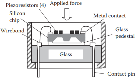
It uses four piezoresistors to measure the stress in a silicon diaphragm caused by the force or pressure of the media. These four piezoresistors are connected electrically to form a Wheatstone bridge. At the corners of the diaphragm, five 0.024-mm-diameter gold bond wires (ultrasonically ball bonded to the sensor) allow electrical connections to the bridge.
The sensor has a resonant frequency above 150 kHz, which also meets the stringent combustion requirements. This sensor can withstand the engine’s harsh environment—extreme operating temperature of 500°C and high vibration.
Piezoresistive Flow Rate Sensor: Flow rate can be measured using a variety of methods. One technique is to take the differential pressure across two points in a flowing medium (e.g., one at a static point and one in the flow stream). Pitot tubes operate based on this principle and have long been used to measure flow rates. Another way is to use the Venturi effect by placing a restriction in the flow path and measuring the pressure difference.
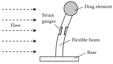
Figure 10, shows a third means to measure flow rate—a bending vane with an attached piezoresistive strain gauge, whose resistance change is proportional to the flow rate and is measured using a Wheatstone bridge circuit.
A piezoresistive flow rate sensor can measure both air or water flow rate in one, two, or three dimensions and also it can detect sporadic, multidimensional, or turbulent flow.
Piezoresistive Blood Pressure Sensor: A silicon piezoresistive sensor can also be used for intravascular blood pressure monitoring .
When the silicon piezoresistive element (directly attached to a stainless-steel plunger) is under an applied force or pressure, the resistance of the silicon element increases, providing a low-cost, extremely compact, and fast-response blood measurement method.
Thanks for reading about “Characteristics of Strain Gauges”.