The Wiegand effect relates to the nonlinear magnetization behavior of a Wiegand wire that switches its polarity under a strong magnetic field. A Wiegand wire is a low-carbon Vicalloy (a family of cobalt–iron–vanadium alloys) wire, typically consisting of 52% cobalt, 37.37% iron, 10% vanadium, 0.4% manganese, 0.2% silicon, and only 0.03% carbon.
The features of a Wiegand wire are that it is short in length, about 0.010 in. in diameter, and magnetically “soft” in its core and magnetically “hard” on its shell. The soft-core, hard-shell Wiegand wire is obtained through a series of unique processes—a fully annealed process followed by a patented coldworking process (a series of twisting and untwisting operations to cold-work on the outer shell of the wire). Thus, the Wiegand wire has a very low magnetic coercivity within the wire and a very high magnetic coercivity on its outer shell.
When a magnetic field is present near the wire, the high coercivity outer shell excludes the magnetic field from the inner soft core until a magnetic threshold is reached, whereupon the entire wire—both the outer shell and inner core—rapidly switches its magnetization polarity.
This switchover occurs in a few microseconds, and is called the Wiegand effect. Once the Wiegand wire has flipped magnetization, it will retain that magnetization until a large magnetic field is applied in the opposite direction to flip it again.
Wiegand Sensor Working Principle
The significance of the Wiegand effect is its big pulse output generated during the magnetization switching of a Wiegand wire. A typical output of a Wiegand sensor is 2 – 6 V (with a typical 10 µs pulse width), which is several-orders-of-magnitude increase over a similar coil with a non-Wiegand core.
This high output voltage plus the high magnetic field threshold that controls when to switch, making a Wiegand sensor one of the most sensitive and reliable sensors.
If an alternating magnetic field (generated by an AC excitation current or by one rotating magnet), instead of a static magnetic field, is around a Wiegand wire, an alternating switching with alternating pulse output can be created. There are two modes of switchings: symmetric switching and asymmetric switching.
In the symmetric mode, the Wiegand wire is magnetized and triggered by an alternating positive and negative magnetic field of equal strength. In the asymmetrical mode (the optimum driving condition), the Wiegand wire is magnetized and triggered by an alternating magnetic field of opposite polarity but with unequal strength, resulting in a large pulse generated in only one direction of the field.
In this situation, the magnetization direction of the magnetically soft core reverses, while the magnetization of the magnetically hard outer shell remains unchanged.
A Wiegand sensor can also be made to have the magnitude of the output pulse proportional to the switching rate of magnetization.
Figure 1a shows a Wiegand sensor in an alternating magnetic field (created by an AC excitation current). Its two terminals are for the pulse output. The pulse is caused by a large Barkhausen jump when the core’s magnetic field switches its polarity, and this voltage pulse is independent of the rate of the field change. An eddy current damper determines the pulse width.
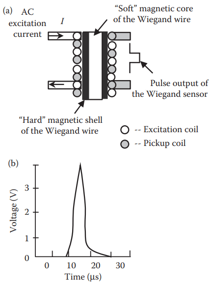
A typical shape of the Wiegand pulse is shown in Figure 1b. The magnitude of the pulse is about 3.7 V and the pulse width is about 10 µs.
Applications of Wiegand Sensors
Wiegand effect sensors can be used in speed measurements, antilock brakers, position indicators, and anemometers. They can also be used for security by attaching them to access cards or antitheft labels.
Figure 2 shows three Wiegand sensor designs for speed measurements. Figure 2a is a rotating object with several magnets placed on its surface (the number of the magnets depends on the measurement accuracy requirement).
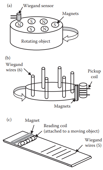
When the object rotates, the Wiegand sensor will produce a positive or negative voltage pulse depending on which magnetic pole (north or south) triggers the sensor. By counting how many pulses are generated, the speed of the object can be determined. The air gap between the sensor and the magnets can be as much as 1 in., depending on the strength of each magnet.
In Figure 2b, the pulses are generated by a rotating drum (with Wiegand wires embedded in it) that passes through a fixed magnetic field. The output of this sensor is about 2 V with a pulse width of 10 μs, which has a lower pulse voltage than design (a). This is because the pickup coil is wound around the read head instead of the Wiegand wires. The advantage of design (b) is that it can indicate the direction of rotation with all positive pulses in one direction and all negative pulses in the other direction.
Figure 2c is a linear design of Wiegand wires. The sensor can detect the linear motion of an object (attached by a reading coil) and can produce positive or negative pulses depending on the direction in which the object moves.
Thanks for reading about “wiegand sensor working principle”.