The Kirchhoff’s Laws are very useful in solving electrical networks which may not be easily solved by Ohm’s Law. In this article, I will describe the Kirchhoff’s current law and will show some kirchhoff’s current law examples to make this law easily understandable.
Kirchhoff’s current law states the following:
The summation of currents entering a node is equal to the summation of currents leaving the node.
An analogy that helps us understand the principle of Kirchhoff’s current law is the flow of water. When water flows in a closed pipe, the amount of water entering a particular point in the pipe is exactly equal to the amount of water leaving, since there is no loss.
In mathematical form, Kirchhoff’s current law is stated as follows:
Σ Ientering node = Σ Ileaving node
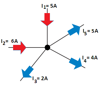
Figure 1 is an illustration of Kirchhoff’s current law. Here we see that the node has two currents entering, I1 = 5 A and I2 = 6 A, and three currents leaving, I3 = 2 A, I4 = 4 A, and I5 = 5 A. Now we can see that above Equation applies in the illustration, namely,
Σ Ientering node = Σ Ileaving node
I1 + I2 = I3 + I4 + I5
5 A + 6 A = 2 A + 4 A + 5 A
11 A = 11 A
When we analyze a given circuit, we are unsure of the direction of current through a particular element within the circuit. In such cases, we assume a reference direction and base further calculations on this assumption.
If our assumption is incorrect, calculations will show that the current has a negative sign. The negative sign simply indicates that the current is in fact opposite to the direction selected as the reference. The following example illustrates this very important concept.
Kirchhoff’s Current Law Examples
Example: Determine the magnitude and correct direction of the currents I3 and I5 for the network of Figure 2.
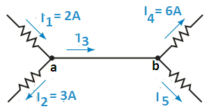
Solution: Although points a and b are in fact the same node, we treat the points as two separate nodes with 0 resistance between them.
Since Kirchhoff’s current law must be valid at point a, we have the following expression for this node:
I1 = I2 + I3
I3 = I1 – I2 = 2 A – 3 A = –1 A
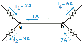
Notice that the reference direction of current I3 was taken to be from a to b, while the negative sign indicates that the current is in fact from b to a.
Similarly, using Kirchhoff’s current law at point b gives
I3 = I4 + I5
Which gives current I5 as I5 = I3 – I4 = –1 A – 6 A = –7 A
The negative sign indicates that the current I5 is actually toward node b rather than away from the node. The actual directions and magnitudes of the currents are illustrated in Figure 3.
Example: Find the magnitudes of the unknown currents for the circuit of Figure 4.
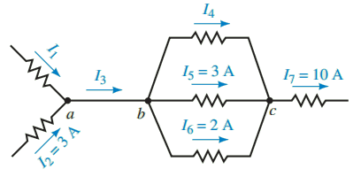
Solution: If we consider point a, we see that there are two unknown currents, I1 and I3. Since there is no way to solve for these values, we examine the currents at point b, where we again have two unknown currents, I3 and I4. Finally, we observe that at point c there is only one unknown, I4. Using Kirchhoff’s current law we solve for the unknown current as follows:
I4 + 3 A + 2 A = 10 A
Therefore,
I4 = 10 A – 3 A – 2 A = 5 A
Now we can see that at point b the current entering is
I3 = 5 A + 3 A + 2 A = 10 A
And finally, by applying Kirchhoff’s current law at point a, we determine that the current I1 is
I1 = 10 A – 3 A = 7 A
Example: Determine the unknown currents in the network of Figure 5.
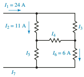
Solution: We first assume reference directions for the unknown currents in the network. Since we may use the analogy of water moving through conduits, we can easily assign directions for the currents I3, I5, and I7.
However, the direction for the current I4 is not as easily determined, so we arbitrarily assume that its direction is to the right. Figure 6 shows the various nodes and the assumed current directions.
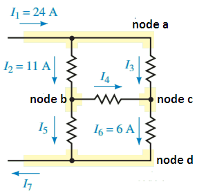
By examining the network, we see that there is only a single source of current I1 = 24 A. Using the analogy of water pipes, we conclude that the current leaving the network is I7 = I1 = 24 A.
Now, applying Kirchhoff’s current law to node a, we calculate the current I3 as follows:
I1 = I2 + I3
Therefore,
I3 = I1 – I2 = 24 A – 11 A = 13 A
Similarly, at node c, we have
I3 + I4 = I6
Therefore, I4 = I6 – I3 = 6 A – 13 A = – 7 A
Although the current I4 is opposite to the assumed reference direction, we do not change its direction for further calculations. We use the original direction together with the negative sign; otherwise the calculations would be needlessly complicated.
Applying Kirchhoff’s current law at node b, we get I2 = I4 + I5
which gives
I5 = I2 – I4 = 11 A – (-7 A) = 18 A
Finally, applying Kirchhoff’s current law at node d gives
I5 + I6 = I7
Resulting in
I7 = I5 + I6 = 18 A + 6 A = 24 A
Thanks for reading about “Kirchhoff’s current law examples”.