Thevenin’s theorem is very useful in solving electrical networks which may not be easily solved by other methods. In this article, I will discuss this theorem and show some of the thevenin theorem examples to make this theorem easily understandable.
Thévenin’s theorem is a circuit analysis technique that reduces any linear bilateral network to an equivalent circuit having only one voltage source and one series resistor.
The resulting two-terminal circuit is equivalent to the original circuit when connected to any external branch or component. In summary, Thévenin’s theorem is simplified as follows:
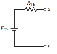
Any linear bilateral network may be reduced to a simplified two-terminal circuit consisting of a single voltage source in series with a single resistor as shown in Figure 1.
A linear network, remember, is any network that consists of components having a linear (straight-line) relationship between voltage and current. A resistor is a good example of a linear component since the voltage across a resistor increases proportionally to an increase in current through the resistor.
Voltage and current sources are also linear components. In the case of a voltage source, the voltage remains constant, although current through the source may change.
A bilateral network is any network that operates in the same manner regardless of the direction of current in the network. Again, a resistor is a good example of a bilateral component, since the magnitude of current through the resistor is not dependent upon the polarity of voltage across the component.
Wheareas, a diode is not a bilateral component, since the magnitude of current through the device is dependent upon the polarity of the voltage applied across the diode.
Steps to Find Thevenin Equivalent: The following steps provide a technique that converts any circuit into its Thévenin equivalent:
- Identify and remove the load from the circuit.
- Label the resulting two terminals. We will label them as a and b, although any notation may be used.
- Set all sources in the circuit to zero. Voltage sources are set to zero by replacing them with short circuits (zero volts). Current sources are set to zero by replacing them with open circuits (zero amps).
- Determine the Thevenin equivalent resistance, RTh, by calculating the resistance “seen” between terminals a and b. It may be necessary to redraw the circuit to simplify this step.
- Replace the sources removed in Step 3, and determine the open-circuit voltage between the terminals. If the circuit has more than one source, it may be necessary to use the superposition theorem. In that case, it will be necessary to determine the open-circuit voltage due to each source separately and then determine the combined effect. The resulting open-circuit voltage will be the value of the Thévenin voltage, ETh.
- Draw the Thevenin equivalent circuit using the resistance determined in Step 4 and the voltage calculated in Step 5. As part of the resulting circuit, include that portion of the network removed in Step 1.
Thevenin Theorem Examples
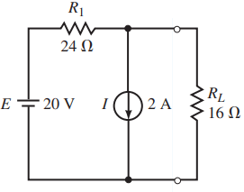
Example: Determine the Thevenin equivalent circuit external to the resistor RL for the circuit of Figure 2. Use the Thevenin equivalent circuit to calculate the current through RL.
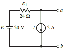
Solution: Steps 1 and 2: Removing the load resistor from the circuit and labelling the remaining terminals, we obtain the circuit shown in Figure 3.
Step 3: Setting the sources to zero, we have the circuit shown in Figure 4.
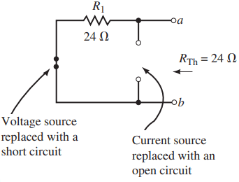
Step 4: The Thévenin resistance between the terminals is RTh 24 Ω .
Step 5: From Figure 3, the open-circuit voltage between terminals a and b is found as Vab = 20 V – (24 Ω)(2 A) = – 28.0 V
Step 6: The resulting Thévenin equivalent circuit is shown in Figure 5
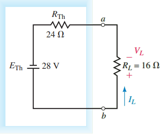
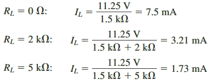
Using this Thévenin equivalent circuit, we easily find the current through RL as
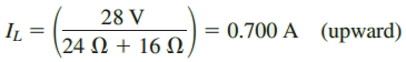
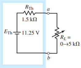
Example: Find the Thévenin equivalent circuit of the indicated area in Figure 6. Using the equivalent circuit, determine the current through the load resistor when RL = 0, RL = 2 kΩ, and RL 5 kΩ.
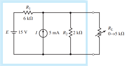
Solution: Steps 1, 2, and 3: After removing the load, labelling the terminals, and setting the sources to zero, we have the circuit shown in Figure 7.
Step 4: The Thévenin resistance of the circuit is RTh = 6 kΩ ll 2 kΩ = 1.5 kΩ
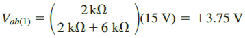
Step 5: Although several methods are possible, we will use the superposition theorem to find the open-circuit voltage Vab. Figure 8 shows the circuit for determining the contribution due to the 15-V source.
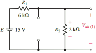
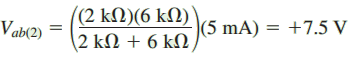
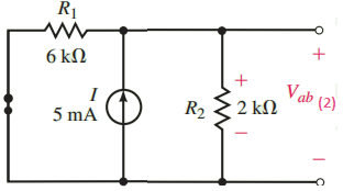
Figure 9 shows the circuit for determining the contribution due to the 5-mA source.
The Thévenin equivalent voltage is
ETh = Vab(1) + Vab(2) = 3.75 V + 7.5 V = 11.25 V
Step 6: The resulting Thévenin equivalent circuit is shown in Figure 10.
Thevenin Theorem Examples
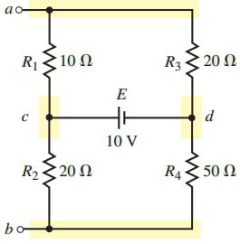
Example: Find the Thévenin equivalent circuit external to R5 in the circuit in Figure 11. Use the equivalent circuit to determine the current through the resistor.
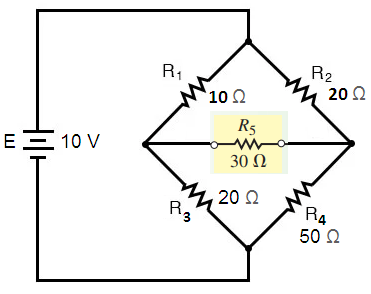
Solution: Notice that the circuit is an unbalanced bridge circuit. If we use other techniques to solve this problem, we would need to solve either three mesh equations or three nodal equations. So, we going to solve this problem with the help of Thévenin theorm.
Steps 1 and 2: Removing the resistor R5 from the circuit and labelling the two terminals a and b, we obtain the circuit shown in Figure 12.
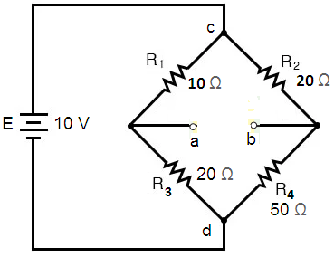
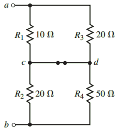
By examining the circuit shown in Figure 12, we see that it is no simple task to determine the equivalent circuit between terminals a and b. The process is simplified by redrawing the circuit as illustrated in Figure 13.
Notice that the circuit of Figure 13 has nodes a and b conveniently shown at the top and bottom of the circuit.
Additional nodes (node c and node d) are added to simplify the task of correctly placing resistors between the nodes.
After simplifying a circuit, it is always a good idea to ensure that the resulting circuit is indeed an equivalent circuit.
You may verify the equivalence of the two circuits by confirming that each component is connected between the same nodes for each circuit.
Now that we have a circuit that is easier to analyze, we find the Thévenin equivalent of the resultant.
Step 3: Setting the voltage source to zero by replacing it with a short, we obtain the circuit shown in Figure 14.
Step 4: The resulting Thévenin resistance is
RTh = 10 ΩII20 Ω + 20 ΩII50 Ω = 6.67 Ω + 14.29 Ω = 20.95 Ω
Step 5: The open-circuit voltage between terminals a and b is found by first indicating the loop currents I1 and I2 in the circuit of Figure 15.
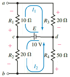
Because the voltage source E provides a constant voltage across the resistor combinations R1-R3 and R2-R4, we simply use the voltage divider rule to determine the voltage across the various components:
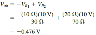
Note: The preceding technique could not be used if the source had some series resistance, since then the voltage provided to resistor combinations R1-R3 and R2-R4 would no longer be the entire supply voltage but rather would be dependent upon the value of the series resistance of the source.
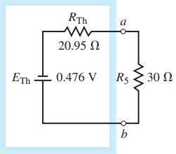
Step 6: The resulting Thévenin circuit is shown in Figure 16. From the circuit of Figure 16, it is now possible to calculate the current through the resistor R5 as
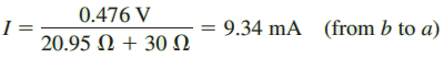
This example illustrates the importance of labelling the terminals that remain after a component or branch is removed. If we had not labelled the terminals and drawn an equivalent circuit, the current through R5 would not have been found as easily.
Thanks for reading about “thevenin theorem examples”.