Generally, it can be stated that a circuit breaker is intended to protect the electrical conductors in the circuit from overheating. It can also be stated that the equipment grounding conductor (EGC) is required by the NEC to be connected so that a low impedance fault current path is provided for the main purpose of removing the voltage from metal parts that are subject to being contacted by people.
In other words, breakers protect the circuit conductors, and the equipment-grounding conductor (for a grounded system) protects personnel from indirect–fault-abnormal type contact with current-carrying conductors. This is accomplished by sensing a level of current less than what the human body can safely withstand.
People do not normally make indirect, unintended, or accidental contact with current-carrying components. Circuit protective devices such as fuses and circuit breakers will not keep a person from getting shocked, hurt, or even killed by direct intentional contact.
Personnel Protective Devices
People are killed by electricity almost daily by systems that have good fuses and circuit breakers. There is a family of protective devices that can be called “personnel protective devices,” indicating that their primary purpose is to protect personnel, neither electrical conductors nor equipment.
These devices are known by an “alphabet soup” listing, such as AFCI (for arc fault circuit interrupters), GFCI, (for ground fault circuit interrupters), and so on. While there are some exceptions, generally by design, these devices operate when they sense a very small level of current imbalance or flow where it should not be present. Some of these devices (AFCIs) may look at the waveform of the current passing through the device.
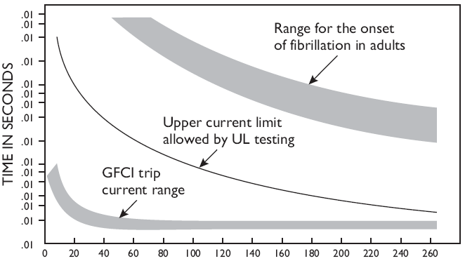
Devices that sense a current imbalance are known as residual current devices (RCDs) and ground fault circuits (GFCs). This family of devices, by design, has trip points well below those that can cause harm to human beings. That is, they trip when the current sensed is in the milliamp (one-thousandth of one ampere) range. These devices operate on a current much smaller than a circuit breaker will. They open the protected circuit between 25 and 40 milliseconds. That is, in less time than the onset of a medical condition known as ventricular fibrillation. This is an irregularity of the heartbeat in which the fibers of the heart muscles work without overall coordination, failing the heart to pump blood. If the condition is significant, as is the case when one is electrically shocked, the terminal result is loss of life.
Some members of this family of devices may have setpoints well above those that can protect people [4 to 6 milliamperes (mA)], that is, setting in the area above 30 mA to as high as 500 mA. An RCD that is intended to protect an appliance power cord will typically have a setting of some 30 mA.
Some of these devices can offer protection even when an equipment grounding conductor is not present, as they operate not on current flow over the EGC, but upon a current imbalance between the two normal current-carrying conductors of the circuit, such as the hot and the neutral.
Devices with setpoints in the hundreds of milliamperes provide fire protection by limiting the energy flow to below that required to start a fire under specified test conditions. These devices may automatically close (non-latching) when power is provided to the line side terminals, while others require the device’s reset button to be manually depressed (latching). While the most common types of RCDs are outlet or 120 V single-phase duplex receptacles, four-wire, three-phase models are available. Some of these devices can have downstream loads connected to them in such a manner as to provide RCD protection to other power outlets.
The following is a listing of a few members of this family of personnel protective devices:
- Appliance leakage current interrupter (ALCA)
- Arc fault circuit interrupters (AFCI)
- Equipment leakage circuit interrupter (ELCI)
- Ground fault circuit interrupters (GFCI)
- Ground fault protective equipment (GFPE)
- Immersion detection circuit
- Interrupters (IDCI)
- Leakage current detection interrupters (LCDI)
- Residual current devices (RCD)
A definition of a ground fault circuit interrupter is “a general use device whose function is to interrupt the electric circuit to a load within an established period.” There is a class A GFCI that trips when the ground fault current exceeds 5 mA and there is a class B GFCI that trips when the ground fault current exceeds 20 mA. A class B GFCI with a 20 mA trip level is to be used only for the protection of underwater swimming pool lighting fixtures installed before the adoption of the 1965 National Electrical Code (NEC). When using a class B GFCI, the swimming pool lighting circuit must be disconnected before servicing or relamping the lighting fixture.

Two sections of Figure 1 are of the most interest. First is the typical plot of current and time for a GFCI. The next is the plot of the onset of heart fibrillation for an adult. As can be seen in the figure these devices provide ample safety room for an adult in normal health.
Ground Fault Protection of Equipment
Section 426 – 28 of the NEC requires ground fault protection of equipment for fixed outdoor electric deicing and snow-melting equipment and Section 427 – 22 of the NEC requires the same for electric heat tracing and heating panels. The trip ratings for these devices are usually in the 30 mA range and are not intended as personal-protection devices. Ground fault sensing and relaying equipment is intended for use in electrical power distribution systems rated at a maximum of 600 V.
GFPE devices operate to cause a disconnecting device to open at a predetermined minimum value of ground fault in accordance with the NEC. Ground fault protection of equipment is defined in the NEC in Article 100 as “a system intended to protect equipment from damaging line to ground fault currents by operating to cause a disconnecting means to open all ungrounded conductors of the faulted circuit.” An example of this type of protection requirement is found in Section 230–95 of the NEC. This section requires solidly grounded wye-connected electrical services of more than 150 V to ground but not exceeding 600 V phase-to-phase with main disconnecting means rated at 1,000 A or more, to be provided with GFPE.
Troubleshooting GFCIs
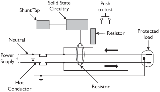
Figure 2 provides a diagram of the major components of a modern GFCI. As an aid to troubleshooting GFCIs, let us begin by reflecting on the not-so-perfect history of GFCIs.

When first delivered to the U.S. market, these devices quickly earned a bad reputation for tripping when no fault was present. This was especially true on construction sites where the leakage from long and multiple extension cords contributed to the tripping of the GFCI. The next trouble to beset the early models was when they were subjected to a high voltage spike.
A review of these types of failures resulted in manufacturers and UL allowing the design to be changed so that a higher milliamperage level would be allowed. The UL listing procedure also allowed the device to fail when closed.
That is, when the electronic components within the GFCI were damaged by a high voltage spike, the push-to-test and reset buttons would continue to move, but the power to the load would not be cut off when the test button was pressed. Consumers and many electricians incorrectly assumed that when the push-to-test and reset buttons were moving, the GFCI was operating properly.
Thankfully several years later, manufacturers and UL again changed the test protocol to require the device to fail open when the electronic components were damaged.
When testing a breaker equipped with a GFCI function, a load such as a radio can be connected to the device to confirm that power is removed when the test button is depressed; when the sound goes off that is proof that the GFCI tripped.
This test does not provide information as to the value of the current at which the device operated. There are test instruments that inject adjustable levels of ground fault current that should be used to confirm that a GFCI is operating in the correct milliamperage range.
When GFCIs first came to the U.S. market, they could be installed incorrectly and would still pass power while not providing the GFCI function. Sometimes, they were installed with the line and load connections reversed. UL now requires that the device not operate when it has been incorrectly wired.
The use of a testing device that confirms that the correct wiring connections have been made to the Hot (ungrounded), Neutral (grounded), and equipment ground connections should be used when testing a GFCI outlet. Some test instruments can also determine the trip current value.
Time and Current Levels Protected by Circuit Breakers
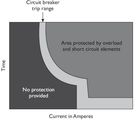
Figure 3 shows the area over which a circuit breaker will operate with normal manufacturing tolerances. All of the current and time combinations to the right of this band will protect over-currents. However, all of the current and time combinations to the left of this band are not protected by the circuit breaker.

The area to the left of the manufacturer’s tolerance band is the area where some other type of personnel protective device must provide protection. This is the area where RDCs, or GFCIs, protect either personnel or equipment. As further research is conducted low current levels are being shown to be capable of providing sufficient energy to start fires.
Arc Fault Circuit Interrupters
By utilizing a solid-state microprocessor and modern algorithms, a new family of protective devices has been created. These protective devices protect nonstandard current flows.
Common devices such as ballast, universal motors, and relays develop current waveforms that are safe. Loose connections, series, and parallel arcing faults are not safe and are not normal. Circuit breakers and GFCIs do not operate to protect the circuit when arc fault conditions occur. Arc fault circuit interrupters (AFCIs) are designed to look at the current flowing and determine if it is safe or unsafe based upon an algorithm.
Currently, the NEC requires that AFCIs be installed in several types of circuits in residences. As the industry gains knowledge of sources of electrical fires and so-called “smart homes,” additional circuit and personnel protective devices utilizing microprocessors will become commonplace. Fuses, MCCBs, RCDs, GFCIs, and AFCIs are not all of the protective devices in use today.
The future of circuit and personnel protection will be filled with more advanced microprocessor-equipped devices. The next generation of protective devices will continue to protect equipment and personnel. These next-generation devices will provide not only evolutionary protection enhancements, but also control, monitoring, scheduling, trending, and alarm functions as well.
Related Posts
- Lightning Arrester Types & Working
- Lightning and Switching Voltage Protection Methods
- Personnel Protective Devices
- How Lightning Arrester Works
- Overvoltage Protection by Lightning Arresters
- Insulation coordination of Electrical Equipment
- MCCB Circuit Breakers
- Differential Protection of Generator & Alternator
- Types of Current Limiting Reactor
- Classification | Types of Protective Relays
- Fuse Selection Criteria
- Protection of Transmission lines by Ground Wires