Power in AC Circuit
The instantaneous power of an AC waveform is given by
p(t) = v(t) · i(t)
Power in a Resistance
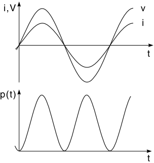
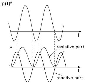
The current and voltage are in phase on the resistor (Fig. 1). For a sinusoidal voltage, the instantaneous power is

Here V and I are the RMS values of the voltage and current. The instantaneous power is a periodic value and is always positive in a resistor. The power consumption oscillates at twice the frequency of the voltage.
Power in a Reactive Element
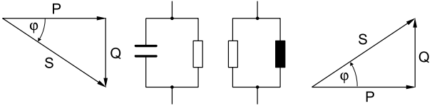
The voltage on a capacitor leads the current by 90o (ϕ = π/2), where ϕ is the phase angle of the voltage, relative to the current. The product p(t) = v(t)i(t) has thus both positive and negative values.
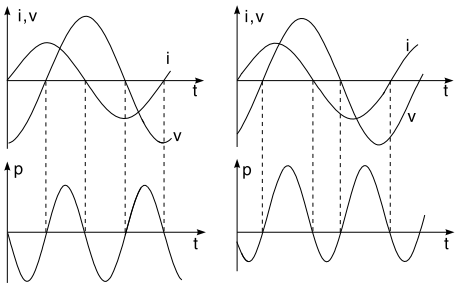
The positive and negative parts of the power curve are equal in magnitude (Fig. 2, left). The capacitor temporarily stores energy and gives it back to the source in the following quarter period. A mixed result exists in the case of a capacitive–resistive load (Fig. 2, right).
One part of the power is consumed in the resistive component of the load, while the other part flows back to the source. The power in an inductive and an inductive–resistive load produces an analogous result.
For sinusoidal current, the instantaneous power can be written as
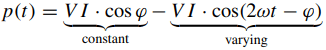
Where ϕ is the phase difference of the voltage with respect to the current.
- The instantaneous power has a constant component and a component that varies at twice the frequency of the current or voltage waveforms. Alternatively, the instantaneous power can be represented by
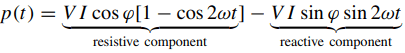
The first term, known as the resistive component, is always positive. The second term alternates between positive and negative values and is known as the reactive component (Fig. 3).
Average Power in AC Circuit
The average power is defined as
When reference is made to power in circuit theory, usually the average power is meant.
Real Power in AC Circuit
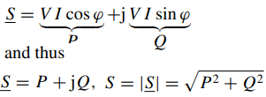
The real power for sinusoidal current and voltage waveforms is given by
P = V · I · cos ϕ
where V and I are the RMS values of the voltage and current. The expression cos ϕ is known as the power factor. The unit of real power is the watt (W).
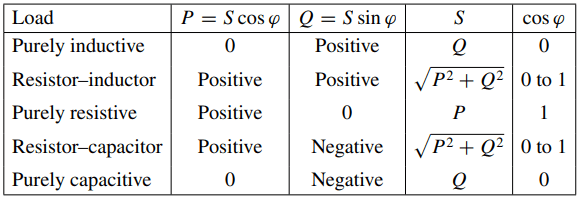
- For purely resistive circuits (ϕ = 0) the power factor cos ϕ = 1, and the real power is P = VI .
- For purely reactive circuits (ϕ = ±90o) the power factor cos ϕ = 0, and the power is thus zero.
- For resistor–capacitor and resistor–inductor loads (−90◦ <ϕ< 90◦) the real power is positive.
- The real power can be converted into other forms of power (heat, mechanical power, etc.).
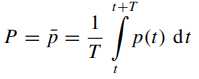
When a complex circuit is represented by its parallel equivalent circuit of a resistance and a reactance the power factor cos ϕ can be modeled in relation to the current. This is known as in-phase or real current (Fig. 4).
Ireal = I . cos ϕ
P = Ireal . V
P = V2 ÷ Rp
- The real power is given by the product of the in-phase current and the RMS voltage. This approach can only be used on parallel combinations, where all of the components experience the same voltage across their terminals.
When a complex circuit is represented by its series equivalent circuit of a resistance and a reactance the power factor cos ϕ can be modeled in relation to the voltage. This is known as in-phase or real voltage.
Vreal = V · cos ϕ
P = Vreal · I
P = I2 · Rr
- The real power is given by the product of the in-phase voltage and the RMS current. This approach can only be used for series combinations, where the same current flows through all of the components.
- The real power is not the product of the in-phase current and the in-phase voltage. These quantities are derived from and applied to different equivalent circuits.
Reactive Power in AC Circuit
The reactive power is defined as
Q = V · I · sin ϕ
where V and I are the RMS values of the voltage and current, and ϕ is the phase difference of the voltage with respect to the current.
The factor sin ϕ is known as the leading or lagging power factor. For inductive loads, this is the lagging power factor, whereas for capacitive loads this is the leading power factor. Lagging and leading describe the lagging or leading of the current with respect to the voltage. The unit for reactive power is the volt-ampere reactive (VAR).
- For purely resistive impedances (ϕ = 0) the reactive power is zero.
- The reactive power in an inductive–resistive load is positive, while in a capacitive–resistive load it is negative.
- Reactive power cannot be converted into other forms of power.
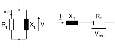
When a complex circuit is represented by its parallel equivalent circuit of a resistance and a reactance the power factor sin ϕ can be modeled in relation to the current. This is known as reactive or out-of-phase current (Fig. 5).
Ireact = −I · sin ϕY
Q = −Ireact · V
Q = V2 ÷ Xp
- The reactive power is given by the product of the negative reactive current and the RMS voltage. This approach can only be used on parallel combinations, where all of the components experience the same voltage across their terminals.
- The negative sign on the reactive current comes from the fact that in the parallel equivalent circuit the phase is expressed with respect to the voltage (ϕY = −ϕZ).
When a complex circuit is represented by its series equivalent circuit of a resistance and a reactance the power factor sin ϕ can be modeled in relation to the current. This is known as reactive or out-of-phase voltage.
Vreact = V · sin ϕ
Q = Vreact · I, Q = I2 · Xr
- The reactive power is given by the product of the out-of-phase voltage and the RMS current. This approach can only be used for series combinations, where the same current flows through all of the components.
- The reactive power is not the product of the out-of-phase current and the out-of-phase voltage. These quantities are derived from different equivalent circuits.
Apparent Power in AC Circuit
The apparent power is defined as
S = V · I
V and I are the RMS values of the voltage and the current, and ϕ is the phase difference of the voltage with respect to the current. The unit of apparent power is the volt-ampere (VA). Thus
P = S · cos ϕ
Q = S · sin ϕ
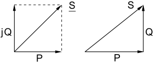
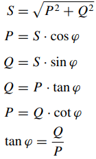
This relation can be best represented geometrically (Fig. 6).
It can be seen from the phasor diagram that
S = √(P2 + Q2)
- Apparent powers from elements with different power factors cannot be added. On the contrary, resistive and reactive powers must be added independently. This yields the overall apparent power.
Complex Power in AC Circuit
Complex power is defined as

- The complex power is the product of the voltage and complex conjugate of the current.

Where ϕ represents the phase shift of the voltage with respect to the current. It follows that
- The real power is the real part of the complex power.
- The reactive power is the imaginary part of the complex power.
- The apparent power is the magnitude of the complex power.
As for other complex quantities, the complex power can be represented by a phasor diagram (Fig. 7).
Overview: AC Power
Reactive Current Compensation
The power factor specifies the fractional contribution of real power P to the apparent power S.
Although the reactive current does not contribute to transferable power, it must nonetheless be transported from the supply to the load. To get usable power from the power source, efforts must be made to minimize the reactive current. These actions are known as power factor correction.
A reactance is placed in parallel with the load and absorbs all of the reactive currents. A capacitor is used for the resistive–inductive loads most often encountered. The reactive current of the capacitor must be equal in magnitude to that of the load. The effect is that the reactive current is diverted from the load to the compensation element, and thus the supply is no longer loaded.
If the reactive current of the compensation element exceeds that of the load, then this is known as overcompensation. In practice, compensation is designed for a power factor of about cos ϕ = 0.9.