Lightning or surge arresters serve the same purpose on an electric circuit or line as a safety valve on a boiler. A safety valve on a boiler relieves a high pressure by allowing steam to blow off until the high pressure is reduced to normal, at which time the safety valve closes again and is ready for the next abnormal condition.
So also is the operation of a lightning or surge arrester. In an electric system, this abnormal pressure takes the form of high-voltage surges in the conductors that may be brought about by the static electricity created by lightning (hence the name, lightning arrester). High-voltage surges may also result from improper switching and other abnormal operations in which the circuit may be involved.
The function of the surge arrester is to allow the discharge of any dangerous over-voltage before it can do damage and then to restore the line to normal operation after the discharge. To accomplish this protective function satisfactorily, arresters must:
- Not allow current to flow to ground so long as the circuit voltage remains normal.
- Provide a path to ground, when the voltage rises to a predetermined valve above normal, to dissipate the energy from the surge without raising the voltage at which the circuit is operating.
- Stop the flow of current to ground, as soon as the voltage drops below the predetermined value, and restore the insulating qualities between the conductor and ground.
- Not be damaged by the discharge and be capable of automatically repeating the discharge action as soon and as frequently as called upon to do so.

How Lightning Arrester Works
The principle upon which lightning or surge arresters usually operate is that when a voltage surge traveling along the conductor reaches the point at which an arrester is installed (usually at some equipment or line to be protected), it finds a lower resistance path to ground than that presented by the equipment or line.
The voltage surge usually breaks down the insulation of the arrester momentarily, allowing the voltage surge to travel to ground and dissipate itself. The insulation of the arrester then recovers its properties and prevents further current from flowing to ground.
Types of Lightning Arrester
Expulsion Type Arrester
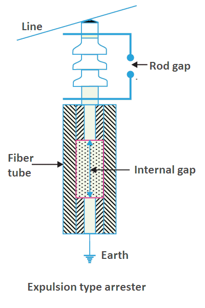
In the expulsion type arrester, there are two series gaps, one of them being the usual gap in series with the valve element. The valve element is essentially another gap in series with the first, although it is contained inside a fiber tube, with an electrode placed at each end of the tube. It is so designed that the voltage breakdown through the tube will be less than that in the insulation of the line or equipment to be protected.

When a voltage surge occurs that is sufficient to spark over the series gap and the gap in the fiber tube, discharge current flows to ground. The arc in the tube attacks the fiber, releasing large volumes of a relatively cool, non-conducting gas.
The gas produced acts not only to extinguish the arc but also builds up pressure that blows the arc out of the tube, returning the arrester to its original condition ready for the next operation. In later types, the external gap is sometimes omitted.
Valve Arresters
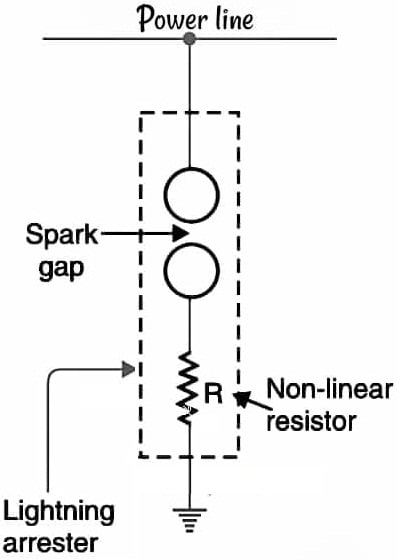
The elementary arrester consists of an air gap in series with a resistive element. The high-voltage surge causes a spark to jump across the air gap and pass through the resistive element to ground.
One resistive element, sometimes referred to as a valve is usually made of a material that provides a low resistance path for the high-voltage surge but presents a high resistance to the flow of line energy at normal voltages.
Arresters of this kind are referred to as valve arresters. Another resistive element consists of an explusion chamber in which the surge, after traveling through the series air gap, permits current to flow through a tube in which the gases formed blow out the arc, thereby restoring the high resistance to the flow of current from normal voltage. The tube or chamber is made of, or lined with, a fiber material.
When this material comes in contact with the arc, it generates gases that increase the pressure in the chamber and help blow out the arc, thereby restoring the arrester to its initial condition ready for another operation.
There are many different types of arresters, all of which have a resistive element and may or may not have a series gap. They differ only in mechanical construction and in the type of resistive element employed.
Autovalve Arrester
In the autovalve arrester, the valve element is made up of ceramic material and conducting particles. The arrester consists of a stack or column of flat discs or electrodes made of this material and separated by thin insulating mica washers; the column is connected through a series gap to the line and ground.

At voltages above the critical value, the short gap between the discs breaks down and current flows. Since the discs are thin and of relatively large area, the resistance through which the discharge current flows is low, even though the resistivity of the discs is comparatively high. When the voltage falls below the critical value, no current will flow and the arrester is returned to its nonconducting state.
Thyrite Arrester
The thyrite arrester consists of a stack of thyrite discs in series with a number of small, interspersed air gaps. Thyrite is a dense, homogeneous, stable, inorganic compound of a ceramic nature and mechanically strong.
It possesses the characteristic of being substantially an insulator at one voltage and then changing to an excellent conductor at a higher voltage; the transition is due to voltage changes only, not to heat as in other valve materials.
For each doubling of the voltage applied, the current that it will pass increases some twelve or more times. These arresters are particularly suited for large high-voltage applications, such as may be found in substations of electric utility systems.
They are built in modules or units, each rated at approximately 11,500 V; the modules are stacked in series to obtain the desired voltage ratings in 11,500 V steps above that rating.
Ground Connection of Lightning Arrester
The effectiveness of any arrester is dependent on a good connection to ground, and such connections must be tested frequently. This cannot be emphasized too strongly as arresters will not function without a proper ground; they are totally useless. Even worse, if they are not known to be in this state, supposedly protected equipment may be severely damaged or completely destroyed.
If possible, arresters should have their own separate ground connection, usually the shortest and most direct path from the arrester to ground. They may also be connected to other common grounds.
Take care, however, about the use of water pipe grounds. The use of plastic water pipe has reduced the effectiveness of water systems as ground sources.
Location of Lightning Arrester
As a good general rule, the arrester should be placed as close as conveniently possible to the equipment, cable, or line that is to be protected. This rule may be modified for any of a number of practical considerations: construction hazards, existence of high trees or other tall obstructions, difficulty of access, and other local factors.
Each installation should be considered individually since what might provide sufficient protection in some localities, on some circuits, and under certain circumstances may not prove sufficient in others.
Other Considerations
In addition to considerations previously discussed, other points should be kept in mind:
- Lightning and other electric surges travel at practically the speed of light, and hence a few feet more or less of circuit have relatively little effect on the protective performance of an arrester.
- An arrester will not necessarily prevent a surge from striking or entering the equipment to be protected. Its function is to discharge fast enough after the surge has been applied to prevent the surge voltage from having enough time to damage the insulation of the equipment to be protected.
- The effectiveness of an arrester depends on, in addition to its internal characteristics, the ability of the ground connection to discharge the abnormal current to the ground.
- The fulfillment of the arrester’s primary function, which is to prevent excessive voltage stress on protected equipment, requires the coordination of the equipment’s insulation characteristics with the arrester’s protective characteristics.
- An arrester is only one of many devices for the protection of a circuit or equipment; other devices include circuit breakers, reclosers, fuses, and the like. For the proper protection of the circuit or equipment, all of these devices must have their characteristics coordinated so that each of them may operate correctly and positively.
Insulation and Arrester Coordination
Schemes for the protection of lines and equipment are usually based on the protection of insulation against failure. The failure of insulation may result from overheating, which first causes the insulation to deteriorate and ultimately to fail.
Overheating is usually allied to the magnitude and duration of the current flowing in the conductors. Protection against it is achieved through the speedy operation of fuses and circuit breakers that cut off the damaging current.
Insulation may also fail from punctures caused by the application of voltages of a magnitude and duration greater than those for which the insulation was designed (including the factors of safety and manufacturing tolerances).
The level of insulation is not based on the supply voltage, which it must withstand under normal operations, but on the peak voltages that might be expected from surges capable of occurring on the electric supply circuits. Such surges usually are caused by lightning or improper switching. Protection is achieved by draining the surge to ground fast enough to prevent damage to the insulation of the equipment or line being protected.
Hence, the characteristics of the arrester must be such that it operates well below the basic insulation level that has to withstand any surges that may be imposed on the equipment or line being protected.
Basic Insulation Level (BIL)
The coordination of insulation requires that the insulation of all components of a system be above a minimum level and that a selected protective device operate satisfactorily below that minimum level, known as the basic insulation level, or BIL. The minimum level of insulation must withstand not only the normal operating voltage applied continuously, but also the surge voltages that may exist for a comparatively very short time but can nevertheless cause damage.
To select the value of this surge voltage, it is necessary to define its rise to its peak value and its fall back to lower values in terms of time, that is, its duration, for, although the peak voltage may rise considerably above the normal voltage, the insulation need sustain its stress only for an extremely short period of time. Put another way, the insulation need not be such as to withstand a continuous stress from the high peak voltage.
A committee representing engineers, utilities, and manufacturers, has therefore, established standards for the characteristics of a voltage surge and recommended insulation levels for equipment of various voltage classes.
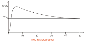
The surge voltage is defined as one that rises to its maximum or crest value in 1.5 microseconds and falls to one-half that value in 40 microseconds (a microsecond is one one-thousandth1/1,000 of a second). This wave is illustrated in following Figure.

For ease of reference, it is designated as a 1.5/40 wave. The steep rising portion of the wave is called the wave front and the receding portion, the wave tail.
Note that the ratio of the BIL (capability to withstand peak surge voltage) to the voltage class (capability to withstand this normal voltage continuously) decreases as the latter increases. The reason is that as the operating voltages become higher and higher, the effect of a surge voltage becomes less and less.
Note also that the BIL for distribution class insulation is less than that for power class, that is, the BIL for utility equipment is less than for consumer equipment.
This difference takes into account that a failure from a surge should preferably occur on the facilities of the utility geared to handle them.
Distribution class arresters are usually restricted to electric distribution circuits. Power class arresters find application at electric stations and transmission lines as well as consumer equipment .
The insulation characteristics of the equipment (its impulse level) are represented by the voltage-time curve that the equipment insulation can withstand. The characteristic of the protecting arrester is also a voltage-time curve that indicates the voltage and time at which the series gaps of the arrester spark over and begin to pass the surge to ground.
The insulation characteristics of the equipment must always be at a higher voltage level than that of the spark-over characteristic of the protecting arrester, and a sufficient voltage difference must exist between the two curves.
The impulse level of equipment must be high enough for the arrester to provide adequate protection and low enough to make insulation costs economically practical.
Although the insulation of electrical equipment may be subject to over-voltages from system faults, switching surges, and occasional higher-than-normal line voltages, these do not usually affect the insulation but may damage the protective device. The major reason for over-voltage protection is to limit the high-voltage effects of lightning surges.
Insulation coordination, therefore, consists of the proper selection of arrester protective characteristics for a particular equipment insulation characteristic so that lightning surges will be discharged to ground without damage to the equipment insulation or to the protective device.
Since electric systems include a number of protective devices, each of which has characteristics of its own, in addition to the circuit conductors and the equipment connected to them, it is essential that the characteristics of all these elements be coordinated for their proper operation and protection.
Lightning Arrester Trouble Shooting
| Trouble | Cause | Suggested remedy |
| Flashover of porcelain | Dirty or polluted surfaces. Insufficient line to ground or to line clearances. Unusual severity of discharge. Incorrect arrester rating. | Clean or replace if necessary. Replace with unit having greater clearances. Replace arrester with one having correct rating. |
| Lightning damage to protected equipment | Arrester rating too high for circuit voltage. Improper arrester location or connections; poor ground Equipment insulation of inadequate impulse strength Air gap set too wide | Replace arrester with one having correct rating Install arrester closer to equipment and obtain a reliable low-resistance ground. Inter-connect all equipment, arresters, lines, cable sheaths, structures, etc., and grounds. Use shorter ground connections. Make sure equipment has minimum standard insulation level. Adjust gap according to specifications |
| Arcing or corona discharge from gap assembly; too frequent spark-overs. | Loose or broken connection Incorrect gap setting Excessive ambient temperature | Tighten or repair connections Set gap according to specifications |
| Excessive operating temperature; discoloration of metal parts. | High internal losses Incorrect arrester rating Loose connections | Relocate to better location. Replace arrester with one having correct rating. Tighten or repair connections |
Summary
- Lightning or surge arresters serve the same purpose on an electric circuit or line as a safety valve on a boiler. When a voltage surge induced by a nearby lightning stroke, or caused by switching, reaches an arrester, it finds a lower resistance path to ground than that presented by the equipment or line. The voltage momentarily breaks down the insulation or the arrester, allowing the surge to travel to ground and dissipate itself.
- The insulation which breaks down momentarily and then restores itself is sometimes called a valve, but sometimes may consist of an air gap and resistor.
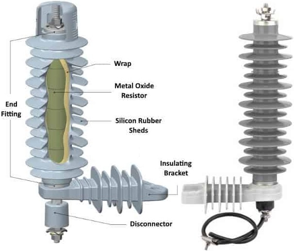
- The valve element may consist of lead oxide pellets, ceramic material containing conducting particles, or such patented materials as thyrite and granulon.
- In an expulsion arrester, the arc is formed within a fiber tube which is attacked by the arc releasing large volumes of relatively cool non-conducting gas that flows out the arc.
- The effectiveness of any arrester is dependent on a good connection to ground, hence such connections must be tested frequently as arresters will not function and are totally useless without a proper ground.
- Arrester characteristics must be coordinated with basic characteristics of the insulation of the lines and equipment they are to protect so that the arrester operates before the insulation is damaged, and before fuses or circuit breakers operate.
- The coordination of insulation requires that the insulation of all components of a system be above minimum level and that a selected protective device operate satisfactorily below the minimum level, known as the basic insulation level, or BIL.
Related Posts
- Lightning Arrester Types & Working
- Lightning and Switching Voltage Protection Methods
- Personnel Protective Devices
- How Lightning Arrester Works
- Overvoltage Protection by Lightning Arresters
- Insulation coordination of Electrical Equipment
- MCCB Circuit Breakers
- Differential Protection of Generator & Alternator
- Types of Current Limiting Reactor
- Classification | Types of Protective Relays
- Fuse Selection Criteria
- Protection of Transmission lines by Ground Wires