Thyristor is a generic term for a broad range of semiconductor components used as an electronic switch. Like a mechanical switch it has only two states: on (conducting) and off (not conducting). Thyristors have no linear in-between state as transistors have.
In addition to switching, they can also be used to adjust the amount of power applied to a load. Thyristors are mainly used where high currents and voltages are involved. They are often used to control alternating currents, where the change of polarity of the current causes the device to automatically switch off. The silicon controlled rectifier and triac are the most frequently used thyristor devices.
Silicon Controlled Rectifier Function
Silicon controlled rectifiers (SCRs) are similar to silicon diodes except for a third terminal, or gate, which controls, or turns on, the SCR.
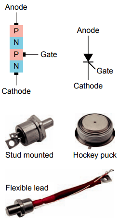
Basically the SCR is a four-layer (PNPN) semiconductor device composed of an anode (A), cathode (K) and gate (G), as shown in Figure 1. Common SCR case styles include stud-mounted, hockey puck, and flexible lead.
SCRs function as switches to turn on or off small or large amounts of power. High-current SCRs that can handle load currents in the thousands of amperes have provisions for some type of heat sink to dissipate the heat generated by the device.
In function, the SCR has much in common with a diode. Like the diode, it conducts current in only one direction when it is forward-biased from anode to cathode. It is unlike the diode because of the presence of a gate (G) lead, which is used to turn the device on. It requires a momentary positive voltage (forward-biased) applied to the gate to switch it on.
When turned on it conducts like a diode for one polarity of current. If not triggered on, it will not conduct a current regardless of whether it is forward-biased.
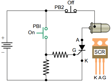
The schematic of an SCR switching circuit that is operated from a DC source is shown in Figure 2. The operation of the circuit can be summarized as follows:
- The anode is connected so that it is positive with respect to the cathode (forward-biased).
- Momentarily closing push button PB1 applies a positive current-limited voltage to the gate of the SCR, which switches the anode-to-cathode circuit into conduction, thus turning the lamp on.
- Once the SCR is on, it stays on, even after the gate voltage is removed. The only way to turn the SCR off is to reduce the anode-cathode current to zero by removing the source voltage from the anode cathode circuit.
- Momentarily pressing push button PB2 opens the anode-to-cathode circuit to switch the lamp off.
- It is important to note that the anode-to-cathode circuit will switch on in just one direction. This occurs only when it is forward biased with the anode positive with respect to the cathode and a positive voltage is applied to the gate.
The problem of SCR turn-off does not occur in AC circuits. The SCR is automatically shut off during each cycle when the AC voltage across the SCR nears zero. As zero voltage is approached, anode current falls below the holding current value. The SCR stays off throughout the entire negative AC cycle because it is reverse biased.
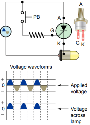
The schematic of an SCR switching circuit that is operated from an AC source is shown in Figure 3. Because the SCR is a rectifier, it can conduct only one-half of the AC input wave. The maximum output delivered to the load, therefore, is 50 percent; its shape is that of a halfwave pulsating DC waveform. The operation of the circuit can be summarized as follows:
- The anode-cathode circuit can be switched on only during the half-cycle when the anode is positive (forward-biased).
- With the push button open, no gate current flows, so the anode-cathode circuit remains off.
- Pressing the push button continuously closed causes the gate-cathode and anode-cathode circuits to be forward-biased at the same time. This produces a halfwave pulsating direct current through the lamp load.
- When the push button is released, the anode- cathode current is automatically shut off when the AC voltage drops to zero on the sine wave.
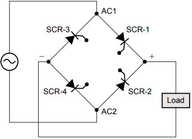
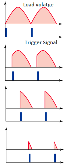
When the SCR is connected to an AC source, it can also be used to vary the amount of power delivered to a load by phase angle control. Figure 4 shows the circuit of a single-phase fully controlled SCR bridge rectifier circuit.
The main purpose of this circuit is to supply a variable DC output voltage to the load. The operation of the circuit can be summarized as follows:
- A pulse trigger is applied to the gate at the instant that the SCR is required to turn on. This pulse is relatively short and would typically be applied to the gate via a pulse transformer.
- The circuit has two pairs of SCRs with SCR-1 and SCR-4 forming one pair and SCR-2 and SCR-3 the other pair.
- During the positive half of the AC input waveform, SCR-1 and SCR-4 can be triggered into conduction.
- During the negative half of the AC input waveform, SCR-2 and SCR-3 can be triggered into conduction.
- Power is regulated by advancing or delaying the point at which each pair of SCRs is turned on within each half-cycle.
- Even though the direction of current through the source alternates from one half-cycle to the other half-cycle, the current through the load remains in the same direction.
SCRs usually fail shorted rather than open. Shorted SCRs can usually be detected with an ohmmeter check. Measure the anode-to-cathode resistance in both the forward and reverse directions; a good SCR should measure near infinity in both directions.
Small and medium-size SCRs can also be gated on with an ohmmeter. Forward bias the SCR with the ohmmeter by connecting its positive lead to the anode and its negative lead to the cathode. Momentarily touch the gate lead to the anode; this will provide a small positive turn-on voltage to the gate and the cathode-to-anode resistance reading will drop to a low value. Even after you remove the gate voltage, the SCR will stay conducting.
Disconnecting the meter leads from the anode or cathode will cause the SCR to revert to its nonconducting state. In this test, the meter resistance acts as the SCR load.
On larger SCRs, the unit may not latch on because the test current is not above the SCR holding current. Special testers are required for larger SCRs in order to provide an adequate value of gate voltage and load the SCR sufficiently to latch on.
Hockey puck SCRs must be compressed in a heat sink (to make up the internal connections to the semiconductor) before they can be tested or operated.
Related Posts
- Operation of Thyristors
- Static Characteristics of SCR | Thyristor
- Silicon Controlled Rectifier Function
- Applications & Characteristics of SCR
- SCR Selection Criteria
- Thyristor | SCR Specifications and Ratings
- Operation of Triac & GTO
- Triac Working
- Characteristics, Operation, & Construction of IGBT
- Freewheeling Diode in Controlled Rectifier
- Reverse Recovery Characteristics of Power Diode