Base Speed and Field Weakening of DC Motor
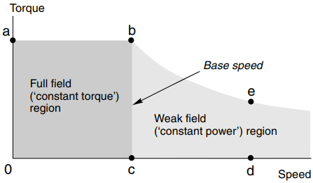
When the field flux is at its full value the speed corresponding to full armature voltage and full current (i.e. the rated full-load condition) is known as base speed (see Figure 1).
The motor can operate at any speed up to base speed, and at any torque (current) up to the rated value by appropriate choice of armature voltage. This full flux region of operation is indicated by the shaded area Oabc in Figure 1, and is often referred to as the ‘constant torque’ region of the torque–speed plane. In this context ‘constant torque’ signifies that at any speed below base speed the motor is capable of producing its full rated torque.
Note that the term constant torque does not mean that the motor will produce constant torque, but rather it signifies that the motor can produce constant torque if required: as we have already seen, it is the mechanical load we apply to the shaft that determines the steady-state torque produced by the motor.
When the current is at maximum (i.e. along the line ab in Figure 1), the torque is at its maximum (rated) value. Since mechanical power is given by torque times speed, the power output along ab is proportional to the speed, and the maximum power thus corresponds to the point b in Figure 1.
At point b, both the voltage and current have their full rated values. To run faster than base speed the field flux must be reduced, as indicated by equation (1).
n = V ÷ KEɸ …..(equation 1)
For example, by halving the flux (and keeping the armature voltage at its full value), the no-load speed is doubled (point d in Figure 1). The increase in speed is however obtained at the expense of available torque, which is proportional to flux times current.
The current is limited to rated value, so if the flux is halved, the speed will double but the maximum torque which can be developed is only half the rated value (point e in Figure 1).
Note that at the point e both the armature voltage and the armature current again have their full rated values, so the power is at maximum, as it was at point b. The power is constant along the curve through b and e, and for this reason the shaded area to the right of the line bc is referred to as the ‘constant power’ region. Obviously, field weakening is only satisfactory for applications which do not demand full torque at high speeds, such as electric traction.
The maximum allowable speed under weak field conditions must be limited (to avoid excessive sparking at the commutator), and is usually indicated on the motor rating plate. A marking of 1200/1750 rev/min, for example, would indicate a base speed of 1200 rev/min, and a maximum speed with field weakening of 1750 rev/min.
The field weakening range varies widely depending on the motor design, but maximum speed rarely exceeds three or four times the base speed.
To sum up, the speed is controlled as follows: .
- Below base speed, the flux is maximum, and the speed is set by the armature voltage. Full torque is available at any speed.
- Above base speed, the armature voltage is at (or close to) maximum and the flux is reduced in order to raise the speed. The maximum torque available reduces in proportion to the flux.
To judge the suitability of a motor for a particular application we need to compare the torque–speed characteristic of the prospective load with the operating diagram for the motor: if the load torque calls for operation outside the shaded areas of Figure 1, a larger motor is clearly called for.
Finally, we should note that according to equation (1), the no-load speed will become infinite if the flux is reduced to zero. This seems unlikely; after all, we have seen that the field is essential for the motor to operate, so it seems unreasonable to imagine that if we removed the field altogether, the speed would rise to infinity.
In fact, the explanation lies in the assumption that ‘no-load’ for a real motor means zero torque. If we could make a motor which had no friction torque whatsoever, the speed would indeed continue to rise as we reduced the field flux towards zero.
But as we reduced the flux, the torque per ampere of armature current would become smaller and smaller, so in a real machine with friction, there will come a point where the torque being produced by the motor is equal to the friction torque, and the speed will therefore be limited.
Nevertheless, it is quite dangerous to open circuit the field winding, especially in a large unloaded motor. There may be sufficient ‘residual’ magnetism left in the poles to produce significant accelerating torque to lead to a run-away situation.
Usually, field and armature circuits are interlocked so that if the field is lost, the armature circuit is switched off automatically.
Armature Reaction
In addition to deliberate field-weakening, as discussed above, the flux in a d.c. machine can be weakened by an effect known as ‘armature reaction’. As its name implies, armature reaction relates to the influence that the armature MMF has on the flux in the machine: in small machines it is negligible, but in large machines the unwelcome field weakening caused by armature reaction is sufficient to warrant extra design features to combat it. A full discussion would be well beyond the needs of most users, but a brief explanation is included for the sake of completeness.

The way armature reaction occurs can best be appreciated by looking at Figure 2 and noting that the MMF of the armature conductors acts along the axis defined by the brushes, i.e. the armature MMF acts in quadrature to the main flux axis which lies along the stator poles.
The reluctance in the quadrature direction is high because of the large air spaces that the flux has to cross, so despite the fact that the rotor MMF at full current can be very large, the quadrature flux is relatively small; and because it is perpendicular to the main flux, the average value of the latter would not be expected to be affected by the quadrature flux, even though part of the path of the reaction flux is shared with the main flux as it passes (horizontally in Figure 2) through the main pole-pieces.
A similar matter was addressed in relation to the primitive machine in previous article. There it was explained that it was not necessary to take account of the flux produced by the conductor itself when calculating the electromagnetic force on it.
And if it were not for the nonlinear phenomenon of magnetic saturation, the armature reaction flux would have no effect on the average value of the main flux in the machine shown in Figure 2: the flux density on one edge of the pole-pieces would be increased by the presence of the reaction flux, but decreased by the same amount on the other edge, leaving the average of the main flux unchanged.
However if the iron in the main magnetic circuit is already some way into saturation, the presence of the rotor MMF will cause less of an increase on one edge than it causes by way of decrease on the other, and there will be a nett reduction in main flux.
We know that reducing the flux leads to an increase in speed, so we can now see that in a machine with pronounced armature reaction, when the load on the shaft is increased and the armature current increases to produce more torque, the field is simultaneously reduced and the motor speeds up. Though this behaviour is not a true case of instability, it is not generally regarded as desirable!
Large motors often carry additional windings fitted into slots in the pole-faces and connected in series with the armature. These ‘compensating’ windings produce an MMF in opposition to the armature MMF, thereby reducing or eliminating the armature reaction effect.
Maximum Output Power of DC Motor
We have seen that if the mechanical load on the shaft of the motor increases, the speed falls and the armature current automatically increases until equilibrium of torque is reached and the speed again becomes steady. If the armature voltage is at its maximum (rated) value, and we increase the mechanical load until the current reaches its rated value, we are clearly at full-load, i.e. we are operating at the full speed (determined by voltage) and the full torque (determined by current).
The maximum current is set at the design stage, and reflects the tolerable level of heating of the armature conductors. Clearly if we increase the load on the shaft still more, the current will exceed the safe value, and the motor will begin to overheat.
But the question which this prompts is ‘if it were not for the problem of overheating, could the motor deliver more and more power output, or is there a limit’? We can see straightaway that there will be a maximum by looking at the torque–speed curves in Figure 3.

The mechanical output power is the product of torque and speed, and we see that the power will be zero when either the load torque is zero (i.e. the motor is running light) or the speed is zero (i.e. the motor is stationary). There must be maximum between these two zeroes, and it is easy to show that the peak mechanical power occurs when the speed is half of the no-load speed.
However, this operating condition is only practicable in very small motors: in the majority of motors, the supply would simply not be able to provide the very high current required.
Turning to the question of what determines the theoretical maximum power, we can apply the maximum power transfer theorem (from circuit theory) to the equivalent circuit in Figure 4. The inductance can be ignored because we assume d.c. conditions.

If we regard the armature resistance R as if it were the resistance of the source V, the theorem tells us that in order to transfer maximum power to the load (represented by the motional e.m.f. on the right-hand side of Figure 4) we must make the load ‘look like’ a resistance equal to the source resistance, R.
This condition is obtained when the applied voltage V divides equally so that half of it is dropped across R and the other half is equal to the e.m.f. E. (We note that the condition E = V/2 corresponds to the motor running at half the no-load speed, as stated above.) At maximum power, the current is V/2R, and the mechanical output power (EI) is given by V2/4R.
The expression for the maximum output power is delightfully simple. We might have expected the maximum power to depend on other motor parameters, but in fact it is determined solely by the armature voltage and the armature resistance.
For example, we can say immediately that a 12 V motor with an armature resistance of 1 Ω cannot possibly produce more than 36 W of mechanical output power.
We should of course observe that under maximum power conditions the overall efficiency is only 50% (because an equal power is burned off as heat in the armature resistance); and emphasise again that only very small motors can ever be operated continuously in this condition. For the vast majority of motors, it is of academic interest only because the current (V/2R) will be far too high for the supply.