Operation of DC Servo Drives
The precise meaning of the term ‘servo’ in the context of motors and drives is difficult to pin down. Broadly speaking, if a drive incorporates ‘servo’ in its description, the implication is that it is intended specifically for closed-loop or feedback control, usually of shaft torque, speed, or position.
Early servomechanisms were developed primarily for military applications, and it quickly became apparent that standard d.c. motors were not always suited to precision control. In particular high torque to inertia ratios were needed, together with smooth ripple-free torque.
Motors were therefore developed to meet these exacting requirements, and not surprisingly they were, and still are, much more expensive than their industrial counterparts. Whether the extra expense of a servo motor can be justified depends on the specification, but prospective users should always be on their guard to ensure they are not pressed into an expensive purchase when a conventional industrial drive could cope perfectly well.
The majority of servo drives are sold in modular form, consisting of a high-performance permanent magnet motor, often with an integral tachogenerator, and a chopper-type power amplifier module. The drive amplifier normally requires a separate regulated d.c. power supply, if, as is normally the case, the power is to be drawn from the a.c. mains.
Continuous output powers range from a few watts up to perhaps 2–3 kW, with voltages of 12, 24, 48, and multiples of 50 V being standard.
Servo Motors
Although there is no sharp dividing line between servo motors and ordinary motors, the servo type will be intended for use in applications which require rapid acceleration and deceleration. The design of the motor will reflect this by catering for intermittent currents (and hence torques) of many times the continuously rated value.
Because most servo motors are small, their armature resistances are relatively high: the short-circuit (locked-rotor) current at full armature voltage is therefore perhaps only five times the continuously rated current, and the drive amplifier will normally be selected so that it can cope with this condition without difficulty, giving the motor a very rapid acceleration from rest.
The even more arduous condition in which the full armature voltage is suddenly reversed with the motor running at full speed is also quite normal. (Both of these modes of operation would of course be quite unthinkable with a large d.c. motor, because of the huge currents which would flow as a result of the much lower per-unit armature resistance.)
Because the drive amplifier must have a high current capability to provide for the high accelerations demanded, it is not normally necessary to employ an inner current-loop of the type discussed earlier.
In order to maximise acceleration, the rotor inertia must be minimised, and one obvious way to achieve this is to construct a motor in which only the electric circuit (conductors) on the rotor move, the magnetic part (either iron or permanent magnet) remaining stationary. This principle is adopted in ‘ironless rotor’ and ‘printed armature’ motors.
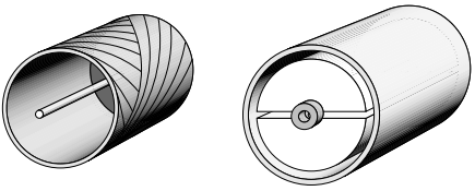
In the ironless rotor or moving-coil type (Figure 1) the armature conductors are formed as a thin-walled cylinder consisting essentially of nothing more than varnished wires wound in skewed form together with the disc-type commutator.
Inside the armature sits a 2-pole (upper N, lower S) permanent magnet, which provides the radial flux, and outside it is a steel cylindrical shell which completes the magnetic circuit.
Needless to say the absence of slots to support the armature winding results in a relatively fragile structure, which is therefore limited to diameters of not much over 1 cm. Because of their small size they are often known as micromotors, and are very widely used in cameras, video systems, card readers etc.
The printed armature type is altogether more robust, and is made in sizes up to a few kilowatts. They are generally made in disc or pancake form, with the direction of flux axial and the armature current radial. The armature conductors resemble spokes on a wheel; the conductors themselves being formed on a lightweight disc. Early versions were made by using printed-circuit techniques, but pressed fabrication is now more common.
Since there are usually at least 100 armature conductors, the torque remains almost constant as the rotor turns, which allows them to produce very smooth rotation at low speed.
Inertia and armature inductance are low, giving a good dynamic response, and the short and fat shape makes them suitable for applications such as machine tools and disc drives where axial space is at a premium.
Position Control of DC Servo Drives
As mentioned earlier many servo motors are used in closed-loop position control applications, so it is appropriate to look briefly at how this is achieved.
In the example shown in Figure 2, the angular position of the output shaft is intended to follow the reference voltage (θref), but it should be clear that if the motor drives a toothed belt linear outputs can also be obtained.
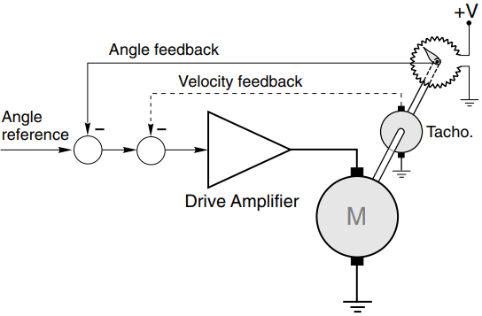
The potentiometer mounted on the output shaft provides a feedback voltage proportional to the actual position of the output shaft. The voltage from this potentiometer must be a linear function of angle, and must not vary with temperature, otherwise the accuracy of the system will be in doubt.
The feedback voltage (representing the actual angle of the shaft) is subtracted from the reference voltage (representing the desired position) and the resulting position error signal is amplified and used to drive the motor so as to rotate the output shaft in the desired direction.
When the output shaft reaches the target position, the position error becomes zero, no voltage is applied to the motor, and the output shaft remains at rest. Any attempt to physically move the output shaft from its target position immediately creates a position error and a restoring torque is applied by the motor.The dynamic performance of the simple scheme described above is very unsatisfactory as it stands.
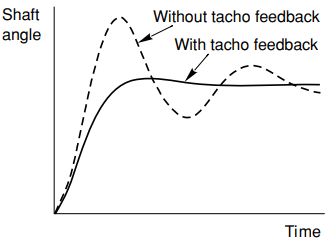
In order to achieve a fast response and to minimise position errors caused by static friction, the gain of the amplifier needs to be high, but this in turn leads to a highly oscillatory response which is usually unacceptable.
For some fixed-load applications, matters can be improved by adding a compensating network at the input to the amplifier, but the best solution is to use ‘tacho’ (speed) feedback (shown dotted in Figure 2) in addition to the main position feedback loop.
Tacho feedback clearly has no effect on the static behaviour (since the voltage from the tacho is proportional to the speed of the motor), but has the effect of increasing the damping of the transient response.
The gain of the amplifier can therefore be made high in order to give a fast response, and the degree of tacho feedback can then be adjusted to provide the required damping (see Figure 3).
Many servo motors have an integral tachogenerator for this purpose. The example above dealt with an analogue scheme in the interests of simplicity, but digital position control schemes are now taking precedence, especially when brushless motors are used.
Complete ‘controllers on a card’ are available as off-the-shelf items, and these offer ease of interface to other systems as well as providing improved flexibility in shaping the dynamic response.
Digitally Controlled Drives
As in all forms of industrial and precision control, digital implementations have replaced analogue circuitry in many electric drive systems, but there are few instances where this has resulted in any real change to the structure of existing drives, and in most cases understanding how the drive functions is still best approached in the first instance by studying the analogue version.
There are of course important systems which are predominantly digital, such as PWM inverter drives and future drives that employ matrix converters may emerge and they are only possible using digital control.
But as far as understanding d.c. drives is concerned, users who have developed a sound understanding of how the analogue version operates will find little to trouble them when considering the digital equivalent. Accordingly this section is limited to the consideration of a few of the advantages offered by digital implementations.
Many drives use digital speed feedback, in which a pulse train generated from a shaft-mounted encoder is compared (using a phase-locked loop) with a reference pulse train whose frequency corresponds to the desired speed.
The reference frequency can easily be made accurate and drift-free; and noise in the encoder signal is easily rejected, so that very precise speed holding can be guaranteed. This is especially important when a number of independent motors must all be driven at identical speed. Phase-locked loops are also used in the firing-pulse synchronising circuits to overcome the problems caused by noise on the mains waveform.
Digital controllers offer freedom from drift, added flexibility (e.g. programmable ramp-up, ramp-down, maximum and minimum speeds etc.), ease of interfacing and linking to other drives and host computers and controllers, and self-tuning.
User-friendly diagnostics represents another benefit, providing the local or remote user with current and historical data on the state of all the key drive variables. Many of these advantages are also offered with drives that continue to employ analogue control in the power electronic stages.