Switched Reluctance Motor Drives
The switched reluctance drive was developed in the 1980s to offer advantages in terms of efficiency, power per unit weight and volume, robustness and operational flexibility. The motor and its associated power-electronic drive must be designed as an integrated package, and optimised for a particular specification, e.g. for maximum overall efficiency with a specific load, or maximum speed range, or peak short-term torque.
Despite being relatively new, the technology has been applied to a wide range of applications including general-purpose industrial drives, compressors, domestic appliances and office and business equipment.
Principle of Operation
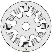
The switched reluctance motor differs from the conventional reluctance motor in that both the rotor and the stator have salient poles. This doubly salient arrangement (as shown in Figure 1) proves to be very effective as far as electromagnetic energy conversion is concerned.

The stator carries coils on each pole, while the rotor, which is made from laminations in the usual way, has no windings or magnets and is therefore cheap to manufacture and extremely robust.
The particular example shown in Figure 1 has 12 stator poles and 8 rotor poles, and represents a widely used arrangement, but other pole combinations are used to suit different applications. In Figure 1, the 12 coils are grouped to form three phases, which are independently energised from a 3-phase converter.
The motor rotates by exciting the phases sequentially in the sequence A, B, C for anticlockwise rotation or A, C, B for clockwise rotation, the ‘nearest’ pair of rotor poles being pulled into alignment with the appropriate stator poles by reluctance torque action.
In Figure 1 the four coils forming phase A are shown by thick line, the polarities of the coil MMFs being indicated by the letters N and S on the back of the core.
Each time a new phase is excited the equilibrium position of the rotor advances by 15o, so after one complete cycle (i.e. each of the three phases has been excited once) the angle turned through is 45o.
The machine therefore rotates once for eight fundamental cycles of supply to the stator windings, so in terms of the relationship between the fundamental supply frequency and the speed of rotation, the machine in Figure 1 behaves as a 16-pole conventional machine.
Readers who are familiar with stepping motors will correctly identify the SR motor as a variable reluctance stepping motor. There are of course important design differences which reflect the different objectives (continuous rotation for the SR, stepwise progression for the stepper), but otherwise the mechanisms of torque production are identical.
However, while the stepper is designed first and foremost for open-loop operation, the SR motor is designed for self-synchronous operation, the phases being switched by signals derived from a shaft-mounted rotor position detector (RPT).
In terms of performance, at all speeds below the base speed continuous operation at full torque is possible. Above the base speed, the flux can no longer be maintained at full amplitude and the available torque reduces with speed.
The operating characteristics are thus very similar to those of the other most important controlled speed drives, but with the added advantage that overall efficiencies are generally a per cent or two higher.
Given that the mechanism of torque production in the switched reluctance motor appears to be very different from that in d.c. machines, induction motors and synchronous machines (all of which exploit the ‘BIl’ force on a conductor in a magnetic field) it might have been expected that one or other type would offer such clear advantages that the other would fade away.
In fact, despite claims and counter claims, there appears to be little to choose between them overall, and one wonders whether the mechanisms of operation are really so fundamentally different as our ingrained ways of looking at things lead us to believe.
Perhaps a visitor from another planet would note the similarity in terms of volume, quantities and disposition of iron and copper, and overall performance, and bring some fresh enlightenment to bear so that we emerge recognising some underlying truth that hitherto has escaped us.
Torque Prediction and Control
If the iron in the magnetic circuit is treated as ideal, analytical expressions can be derived to express the torque of a reluctance motor in terms of the rotor position and the current in the windings.
In practice, however, this analysis is of little real use, not only because switched reluctance motors are designed to operate with high levels of magnetic saturation in parts of the magnetic circuit, but also because, except at low speeds, it is not practicable to achieve specified current profiles.
The fact that high levels of saturation are involved makes the problem of predicting torque at the design stage challenging, but despite the highly non-linear relationships it is possible to compute the flux, current and torque as functions of rotor position, so that optimum control strategies can be devised to meet particular performance specifications.
Unfortunately this complexity means that there is no simple equivalent circuit available to illuminate behaviour. As we saw when we discussed the stepping motor, to maximise the average torque it would (in principle) be desirable to establish the full current in each phase instantaneously, and to remove it instantaneously at the end of each positive torque period.
But, this is not possible even with a small stepping motor, and certainly out of the question for switched reluctance motors (which have much higher inductance) except at low speeds where current chopping is employed.
For most of the speed range, the best that can be done is to apply the full voltage available from the converter at the start of the ‘on’ period, and apply full negative voltage at the end of the pulse by opening both of the switches.
Operation using full positive voltage at the beginning and full negative voltage at the end of the ‘on’ period is referred to as ‘single-pulse’ operation. For all but small motors (of less than say 1 kW) the phase resistance is negligible and consequently the magnitude of the phase flux-linkage is determined by the applied voltage and frequency, as we have seen many times previously with other types of motor.
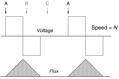
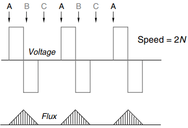
The relationship between the flux-linkage and the voltage is embodied in Faraday’s law. So with the rectangular voltage waveform of single-pulse operation the phase flux linkage waveforms have a very simple triangular shape, as in Figure 2 which shows the waveforms for phase A of a 3-phase motor.
(The waveforms for phases B and C are identical, but are not shown: they are displaced by one third and two thirds of a cycle, as indicated by the arrows.)


The upper half of the diagram represents the situation at speed N, while the lower half corresponds to a speed of 2N.
As can be seen, at the higher speed (high frequency) the ‘on’ period halves, so the amplitude of the flux halves, leading to a reduction in available torque.
It is important to note that these flux waveforms do not depend on the rotor position, but the corresponding current waveforms do because the MMF needed for a given flux depends on the effective reluctance of the magnetic circuit, and this of course varies with the position of the rotor.
To get the most motoring torque for any given phase flux waveform, it is obvious that the rise and fall of the flux must be timed to coincide with the rotor position: ideally, the flux should only be present when it produces positive torque, and be zero whenever it would produce negative torque, but given the delay in build-up of the flux it may be better to switch on early so that the flux reaches a decent level at the point when it can produce the most torque, even if this does lead to some negative torque at the start and finish of the cycle.
The job of the torque control system is to switch each phase on and off at the optimum rotor position in relation to the torque being demanded at the time, and this is done by keeping track of the rotor position using a RPT.
Just what angles constitute the optimum depends on what is to be optimised (e.g. average torque, overall efficiency), and this in turn is decided by reference to the data stored digitally in the controller ‘memory map’ that relates current, flux, rotor position and torque for the particular machine.
Torque control is thus considerably less straightforward than in d.c. drives, where torque is directly proportional to armature current, or induction motor drives where torque is proportional to slip.
Power Converter and Overall Drive Characteristics
An important difference between the SR motor and all other self-synchronous motors is that its full torque capability can be achieved without having to provide for both positive and negative currents in the phases. This is because the torque does not depend on the direction of current in the phase-winding.
The advantage of such ‘unipolar’ drives is that because each of the main switching devices is permanently connected in series with one of the motor windings, there is no possibility of the ‘shoot-through’ fault which is a major headache in the conventional inverter.
Overall closed-loop speed control is obtained in the conventional way with the speed error acting as a torque demand to the torque control system described above. However, in most cases it is not necessary to fit a tacho as the speed feedback signal can be derived from the RPT.
In common with other self-synchronous drives, a wide range of operating characteristics is available. If the input converter is fully controlled, continuous regeneration and full four-quadrant operation is possible, and the usual constant torque, constant power and series type characteristic is regarded as standard.
Low speed torque can be uneven unless special measures are taken to profile the current pulses, but continuous low speed operation is usually better than for most competing systems in terms of overall efficiency.
Reluctance Motors
The reluctance motor is arguably the simplest synchronous motor of all, the rotor consisting simply of a set of laminations shaped so that it tends to align itself with the field produced by the stator.
In these motors, induction motor action is used to get the rotor up to synchronous speed.
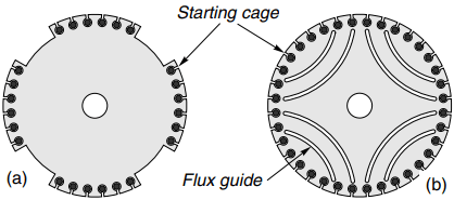
The stator is identical with that of a 3-phase induction motor. A reluctance-type rotor resembles a cage induction motor, with parts of the periphery cut away in order to force the flux from the stator to enter the rotor in the remaining regions where the air-gap is small, as shown in Figure 3.

Alternatively, the ‘preferred flux paths’ can be imposed by removing iron inside the rotor so that the flux is guided along the desired path, as shown in Figure 3(b).
The rotor will tend to align itself with the field, and hence is able to remain synchronised with the travelling field set up by the 3-phase winding on the stator in much the same way as a permanent magnet rotor.
Early reluctance motors were invariably one or two frame sizes bigger than an induction motor for a given power and speed, and had low power factor and poor pull-in performance. As a result they fell from favour except for some special applications such as textile machinery where cheap constant speed motors were required.
Understanding of reluctance motors is now much more advanced, and they can compete on almost equal terms with the induction motor as regards power-output, power factor and efficiency. They are nevertheless relative expensive because they are not produced in large numbers.