Stepping motors are attractive because they can be controlled directly by computers or microcontrollers. Their unique feature is that the output shaft rotates in a series of discrete angular intervals, or steps, one step being taken each time a command pulse is received.
When a definite number of pulses has been supplied, the shaft will have turned through a known angle, and this makes the motor ideally suited for open-loop position control.
The idea of a shaft progressing in a series of steps might conjure up visions of a ponderous device laboriously indexing until the target number of steps has been reached, but this would be quite wrong.
Each step is completed very quickly, usually in a few milliseconds; and when a large number of steps are called for the step command pulses can be delivered rapidly, sometimes as fast as several thousand steps per second. At these high stepping rates the shaft rotation becomes smooth, and the behaviour resembles that of an ordinary motor.
Typical applications include disc head drives, and small numerically controlled machine tool slides, where the motor would drive a lead screw; and print feeds, where the motor might drive directly, or via a belt.
Most stepping motors look very much like conventional motors, and as a general guide we can assume that the torque and power of a stepping motor will be similar to the torque and power of a conventional totally enclosed motor of the same dimensions and speed range.
Step angles are mostly in the range 1.8o–90o, with torques ranging from 1mNm (in a tiny wristwatch motor of 3 mm diameter) up to perhaps 40 Nm in a motor of 15 cm diameter suitable for a machine tool application where speeds of 500 rev/min might be called for. The majority of applications fall between these limits, and use motors that can comfortably be held in the hand.
Open Loop Position Control
A basic stepping motor system is shown in Figure 1. The drive contains the electronic switching circuits, which supply the motor. The output is the angular position of the motor shaft, while the input consists of two low-power digital signals.
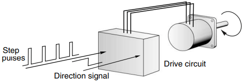
Every time a pulse occurs on the step input line, the motor takes one step, the shaft remaining at its new position until the next step pulse is supplied. The state of the direction line (‘high’ or ‘low’) determines whether the motor steps clockwise or anticlockwise.
A given number of step pulses will therefore cause the output shaft to rotate through a definite angle. This one to one correspondence between pulses and steps is the great attraction of the stepping motor: it provides position control, because the output is the angular position of the output shaft.
It is a digital system, because the total angle turned through is determined by the number of pulses supplied; and it is open-loop because no feedback need be taken from the output shaft.
Generation of Step Pulses and Motor Response
The step pulses may be produced by an oscillator circuit, which itself is controlled by an analogue voltage, digital controller or microprocessor. When a given number of steps is to be taken, the oscillator pulses are gated to the drive and the pulses are counted, until the required number of steps is reached, when the oscillator is gated off.
This is illustrated in Figure 2, for a six-step sequence. There are six-step command pulses, equally spaced in time, and the motor takes one step following each pulse. Three important general features can be identified with reference to Figure 2.
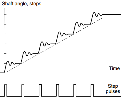
Firstly, although the total angle turned through (six steps) is governed only by the number of pulses, the average speed of the shaft (which is shown by the slope of the broken line in Figure 2) depends on the oscillator frequency. The higher the frequency, the shorter the time taken to complete the six steps.
Secondly, the stepping action is not perfect. The rotor takes a finite time to move from one position to the other, and then overshoots and oscillates before finally coming to rest at the new position. Overall single-step times vary with motor size, step angle and the nature of the load, but are commonly within the range 5–100 ms.
This is often fast enough not to be seen by the unwary newcomer, though individual steps can usually be heard; small motors ‘tick’ when they step, and larger ones make a satisfying ‘click’ or ‘clunk’.
Thirdly, in order to be sure of the absolute position at the end of a stepping sequence, we must know the absolute position at the beginning. This is because a stepping motor is an incremental device.
As long as it is not abused, it will always take one step when a drive pulse is supplied, but in order to keep track of absolute position simply by counting the number of drive pulses (and this is after all the main virtue of the system) we must always start the count from a known datum position.
Normally the step counter will be ‘zeroed’ with the motor shaft at the datum position, and will then count up for clockwise direction, and down for anticlockwise rotation. Provided no steps are lost the number in the step counter will then always indicate the absolute position.
High Speed Running and Ramping of Stepping Motors
The discussion so far has been restricted to operation when the step command pulses are supplied at a constant rate, and with sufficiently long intervals between the pulses to allow the rotor to come to rest between steps.
Very large numbers of small stepping motors in watches and clocks do operate continuously in this way, stepping perhaps once every second, but most commercial and industrial applications call for a more exacting and varied performance. To illustrate the variety of operations which might be involved, and to introduce high-speed running, we can look briefly at a typical industrial application.
A stepping motor-driven table feed on a numerically controlled milling machine nicely illustrates both of the key operational features discussed earlier. These are the ability to control position (by supplying the desired number of steps) and velocity (by controlling the stepping rate). The arrangement is shown diagrammatically in Figure 3.
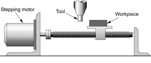
The motor turns a leadscrew connected to the worktable, so that each motor step causes a precise incremental movement of the workpiece relative to the cutting tool. By making the increment small enough, the fact that the motion is discrete rather than continuous will not cause any difficulties in the machining process.
We will assume that we have selected the step angle, the pitch of the leadscrew, and any necessary gearing so as to give a table movement of 0.01 mm per motor step. We will also assume that the necessary step command pulses will be generated by a digital controller or computer, programmed to supply the right number of pulses, at the right speed for the work in hand.
If the machine is a general-purpose one, many different operations will be required.
When taking heavy cuts, or working with hard material, the work will have to be offered to the cutting tool slowly, at say, 0.02 mm/s. The stepping rate will then have to be set to 2 steps/s. If we wish to mill out a slot 1-cm long, we will therefore programme the controller to put out 1000 steps, at a uniform rate of 2 steps per second, and then stop.
On the other hand, the cutting speed in softer material could be much higher, with stepping rates in the range 10–100 steps per second being in order. At the completion of a cut, it will be necessary to traverse the work back to its original position, before starting another cut.
This operation needs to be done as quickly as possible, to minimise unproductive time, and a stepping rate of perhaps 2000 steps per second (or even higher), may be called for.
It was mentioned earlier that a single step (from rest) takes upwards of several milliseconds. It should therefore be clear that if the motor is to run at 2000 steps per second (i.e. 0.5 ms/step), it cannot possibly come to rest between successive steps, as it does at low stepping rates.
Instead, we find in practice that at these high stepping rates, the rotor velocity becomes quite smooth, with hardly any outward hint of its stepwise origins.
Nevertheless, the vital one-to-one correspondence between step command pulses and steps taken by the motor is maintained throughout, and the open-loop position control feature is preserved.
This extraordinary ability to operate at very high stepping rates (up to 20 000 steps per second in some motors), and yet to remain fully in synchronism with the command pulses, is the most striking feature of stepping motor systems.
Operation at high speeds is referred to as ‘slewing’. The transition from single stepping to high-speed slewing is a gradual one and is indicated by the sketches in Figure 4.
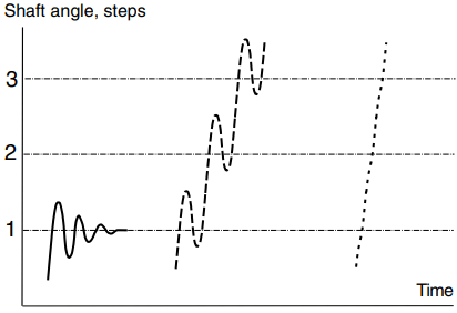
Roughly speaking, the motor will ‘slew’ if its stepping rate is above the frequency of its single-step oscillations. When motors are in the slewing range, they generally emit an audible whine, with a fundamental frequency equal to the stepping rate.
It will come as no surprise to learn that a motor cannot be started from rest and expected to ‘lock on’ directly to a train of command pulses, at say, 2000 steps per second, which is well into the slewing range.
Instead, it has to be started at a more modest stepping rate, before being accelerated (or ‘ramped’) up to speed. In undemanding applications, the ramping can be done slowly, and spread over a large number of steps; but if the high stepping rate has to be reached quickly, the timings of individual step pulses must be very precise.
We may wonder what will happen if the stepping rate is increased too quickly. The answer is simply that the motor will not be able to remain ‘in step’ and will stall. The step command pulses will still be delivered, and the step counter will be accumulating what it believes are motor steps, but, by then, the system will have failed completely.
A similar failure mode will occur if, when the motor is slewing, the train of step pulse is suddenly stopped, instead of being progressively slowed. The stored kinetic energy of the motor (and load) will cause it to overrun, so that the number of motor steps will be greater than the number of command pulses. Failures of this sort are prevented by the use of closed-loop control.
Finally, it is worth mentioning that stepping motors are designed to operate for long periods with their rotor held in a fixed (step) position, and with rated current in the winding (or windings).
We can therefore anticipate that stalling is generally not a problem for a stepping motor, whereas for most other types of motor, stalling results in a collapse of back e.m.f. and a very high current which can rapidly lead to burnout.
Principle of Motor Operation
The principle on which stepping motors are based is very simple. When a bar of iron or steel is suspended so that it is free to rotate in a magnetic field, it will align itself with the field. If the direction of the field is changed, the bar will turn until it is again aligned, by the action of the so-called reluctance torque.
Before exploring constructional details, it is worth saying a little more about reluctance torque.
Reluctance torque originates in the tendency of an iron bar to align itself with magnetic field: if the bar is displaced from its alignment position it experiences a restoring torque.
The rotors of machines that produce torque by reluctance action are therefore designed so that the rotor iron has projections or ‘poles’ (see Figure 5) that align with the magnetic field produced by the stator windings.
All the torque is then produced by reluctance action, because with no conductors on the rotor to carry current.
The two most important types of stepping motor are the variable reluctance (VR) type and the hybrid type. Both types utilise the reluctance principle, the difference between them lying in the method by which the magnetic fields are produced.
In the VR type the fields are produced solely by sets of stationary current-carrying windings. The hybrid type also has sets of windings, but the addition of a permanent magnet (on the rotor) gives rise to the description ‘hybrid’ for this type of motor.
Although both types of motor work on the same basic principle, it turns out in practice that the VR type is attractive for the larger step angles (e.g. 15o, 30o, 45o), while the hybrid tends to be best suited when small angles (e.g. 1.8o, 2.5o) are required.
Variable Reluctance Motor
A simplified diagram of a 30o per step VR stepping motor is shown in Figure 5. The stator is made from a stack of steel laminations, and has six equally spaced projecting poles, or teeth, each carrying a separate coil.
The rotor, which may be solid or laminated, has four projecting teeth, of the same width as the stator teeth. There is a very small air-gap – typically between 0.02 and 0.2 mm – between rotor and stator teeth.
When no current is flowing in any of the stator coils, the rotor will therefore be completely free to rotate.
Diametrically opposite pairs of stator coils are connected in series, such that when one of them acts as a N pole, the other acts as a S pole. There are thus three independent stator circuits, or phases, and each one can be supplied with direct current from the drive circuit (not shown in Figure 5).
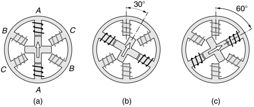
When phase A is energised (as indicated by the thick lines in Figure 5(a)), a magnetic field with its axis along the stator poles of phase A is created. The rotor is therefore attracted into a position where the pair of rotor poles distinguished by the marker arrow line up with the field, i.e. in line with the phase A pole, as shown in Figure 5(a).
When phase A is switched-off, and phase B is switched-on instead, the second pair of rotor poles will be pulled into alignment with the stator poles of phase B, the rotor moving through 30o clockwise to its new step position, as shown in Figure 5(b).
A further clockwise step of 30o will occur when phase B is switched-off and phase C is switched-on. At this stage the original pair of rotor poles come into play again, but this time they are attracted to stator poles C, as shown in Figure 5(c).
By repetitively switching on the stator phases in the sequence ABCA, etc. the rotor will rotate clockwise in 30o steps, while if the sequence is ACBA, etc. it will rotate anticlockwise.
This mode of operation is known as ‘one-phase-on’, and is the simplest way of making the motor step.
Note that the polarity of the energising current is not significant: the motor will be aligned equally well regardless of the direction of current.
An alternative form of VR motor is the multi-stack type, consisting of several (typically three) magnetically independent sections or ‘stacks’ within a single housing.
In a three-stack motor the rotor will consist of three separate toothed sections on a common shaft, each having the same number of equispaced teeth, but with the teeth on each section displaced by one-third of a tooth pitch from its neighbour.
The stator also has three separate stacks each of which looks rather like the stator of a hybrid motor (see Figure 6), with the teeth on each stator pole having the same pitch as the rotor teeth. The three stator stacks have their teeth aligned, and each stator has a winding, which excites all of its poles.
For one-phase-on operation each stator is energised sequentially, so that its respective rotor teeth are pulled into alignment with the stator teeth. Stepping occurs because successive sets of rotor teeth are misaligned by one step.
The principal difference as compared with the single-stack VR motor (see Figure 5) is that all the rotor teeth on any one stack contribute to torque when that particular stack is energised.
The overall utilisation of materials is no better than the singlestack type, however, because only one-third of the material is energised at a time.
Hybrid Motor
A cross-sectional view of a typical 1.8o hybrid motor is shown in Figure 6. The stator has eight main poles, each with five teeth, and each main pole carries a simple coil.
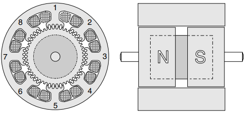
The rotor has two steel end-caps, each with 50 teeth, and separated by a permanent magnet. The rotor teeth have the same pitch as the teeth on the stator poles, and are offset so that the centre-line of a tooth at one end-cap coincides with a slot at the other end-cap.
The permanent magnet is axially magnetised, so that one set of rotor teeth is given a N polarity, and the other a S polarity.
When no current is flowing in the windings, the only source of magnetic flux across the air-gap is the permanent magnet. The magnetic flux crosses the air-gap from the N end-cap into the stator poles, flows axially along the body of the stator, and returns to the magnet by crossing the air-gap to the S end-cap.
If there were no offset between the two sets of rotor teeth, there would be a strong periodic alignment torque when the rotor was turned, and every time a set of stator teeth was in line with the rotor teeth we would obtain a stable equilibrium position. However, there is an offset, and this causes the alignment torque due to the magnet to be almost eliminated.
In practice a small ‘detent’ torque remains, and this can be felt if the shaft is turned when the motor is de-energised: the motor tends to be held in its step positions by the detent torque.
This is sometimes very useful: for example, it is usually enough to hold the rotor stationary when the power is switched-off, so the motor can be left overnight without fear of it being accidentally nudged into to a new position.
The eight coils are connected to form two phase-windings. The coils on poles 1, 3, 5 and 7 form phase A, while those on 2, 4, 6 and 8 form phase B.
When phase A carries positive current stator poles 1 and 5 are magnetised as S, and poles 3 and 7 become N. The offset teeth on the N end of the rotor are attracted to poles 1 and 5 while the offset teeth at the S end of the rotor are attracted into line with the teeth on poles 3 and 7.
To make the rotor step, phase A is switched-off, and phase B is energised with either positive current or negative current, depending on the sense of rotation required. This will cause the rotor to move by one-quarter of a tooth pitch (1.8o) to a new equilibrium (step) position.
The motor is continuously stepped by energising the phases in the sequence +A, -B, -A, +B, +A (clockwise) or +A, +B, -A, -B, +A (anticlockwise). It will be clear from this that a bipolar supply is needed (i.e. one which can furnish +ve or -ve current).
When the motor is operated in this way it is referred to as ‘two-phase, with bipolar supply’.
If a bipolar supply is not available, the same pattern of pole energisation may be achieved in a different way, as long as the motor windings consist of two identical (‘bifilar wound’) coils.
To magnetise pole 1 north, a positive current is fed into one set of phase A coils. But to magnetise pole 1 south, the same positive current is fed into the other set of phase A coils, which have the opposite winding sense.
In total, there are then four separate windings, and when the motor is operated in this way it is referred to as ‘4-phase, with unipolar supply’.
Since each winding only occupies half of the space, the MMF of each winding is only half of that of the full coil, so the thermally rated output is clearly reduced as compared with bipolar operation (for which the whole winding is used).
We round off this section on hybrid motors with a comment on identifying windings, and a warning. If the motor details are not known, it is usually possible to identify bifilar windings by measuring the resistance from the common to the two ends.
If the motor is intended for unipolar drive only, one end of each winding may be commoned inside the casing; for example, a 4-phase unipolar motor may have only five leads, one for each phase and one common.
Wires are also usually colour-coded to indicate the location of the windings; for example, a bifilar winding on one set of poles will have one end red, the other end red and white and the common white.
Finally, it is not advisable to remove the rotor of a hybrid motor because they are magnetised in situ: removal typically causes a 5–10% reduction in magnet flux, with a corresponding reduction in static torque at rated current.
Summary
The construction of stepping motors is simple, the only moving part being the rotor, which has no windings, commutator or brushes: they are therefore robust and reliable. The rotor is held at its step position solely by the action of the magnetic flux between stator and rotor.
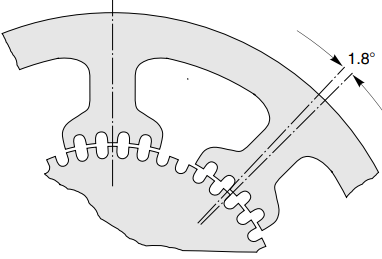
The step angle is a property of the tooth geometry and the arrangement of the stator windings, and accurate punching and assembly of the stator and rotor laminations is therefore necessary to ensure that adjacent step positions are exactly equally spaced. Any errors due to inaccurate punching will be non-cumulative, however.
The step angle is obtained from the expression
Step angle = 360 ÷ (rotor teeth x stator phases)
The VR motor in Figure 5 has four rotor teeth, three stator phase windings and the step angle is therefore 30o, as already shown. It should also be clear from the equation why small angle motors always have to have a large number of rotor teeth.
Probably the most widely used motor is the 200 steps per revolution hybrid type (see Figure 6). This has a 50 tooth rotor, 4-phase stator, and hence a step angle of 1.8o (= 360o÷(50 x 4)).
The magnitude of the aligning torque clearly depends on the magnitude of the current in the phase winding. However, the equilibrium positions itself does not depend on the magnitude of the current, because it is simply the position where the rotor and stator teeth are in line. This property underlines the digital nature of the stepping motor.